3
\$\begingroup\$

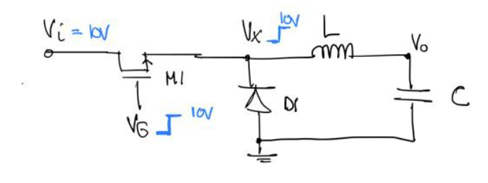
I know that to use an NMOS as a high side, you need a gate boosting circuit! I am just here to check my understanding on what WOULD happen if I did use an NMOS device without a boosting circuit and how exactly the transient turn on behaviour would work:

Off-State

enter image description here

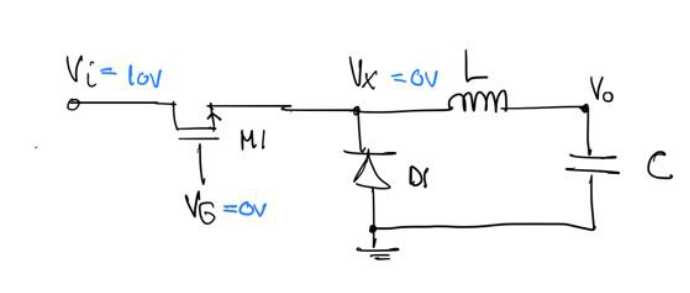
In this state, Vi is 10V. Vg is 0V. Vx is also at 0V because the inductor acts as a short and the capacitor we assume is fully discharged, hence 0V appears at Vx.

Turning On

enter image description here

We now apply a 10V step to the gate of M1. The Vx node was previously at 0V, so as the 10V to the gate of M1 is ramping up to 10V due to a finite rise time - first, a weak inversion layer will be created in M1 channel, a sub-threshold current will begin to flow through M1 and node Vx will be at 10V, turning the device off again?

This is where I am confused. How exactly does Vx get to 10V so that M1 turns off again? Could someone explain to me how much current flows, and the sequence in which things happen here?

Because I know if Vx is at 10V and Vo is at 0V, then the inductor should have a di/dt of 10/L but surely M1 cannot support that much current if it is in sub threshold, so what happens?

\$\endgroup\$
2
  • 1
    \$\begingroup\$ This question is very close to driving high-side MOSFETs in half-bridge circuits. For example: electronics.stackexchange.com/questions/137090/… Howewer, such circuits cannot yield 100% duty cycle \$\endgroup\$
    – Vladimir
    Commented May 15, 2022 at 16:30
  • \$\begingroup\$ The NMOS wouldn't be a switch, it would be a source follower, i.e. a kind of class A amp. \$\endgroup\$
    – user16324
    Commented May 15, 2022 at 21:26

3 Answers 3

4
\$\begingroup\$

The output wont be 10 V and the Mosfet will form a voltage follower (linear region) with a drop equal to its gate threshold voltage.

So the problem is not, that the MOSFET would turn off, but that it will dissipate a lot of power, namely the load current times its gate source voltage necessary for that load current.

This voltage drop is usually 2..3 V, so much more than for the same current through a fully enhanced MOSFET.

\$\endgroup\$
3
  • \$\begingroup\$ So you're saying the MOSFET will act like a linear resistor and VX would never reach 10V and the inductor would pull the current that it wants (( VX - Vout) / L) through this MOSFET resistance which would be large and hence VX never reaches 10V?? \$\endgroup\$ Commented May 15, 2022 at 16:41
  • \$\begingroup\$ @alayoiskgfbfqhxjiw yes. during on the on-time, the MOSFET is in a diode-connected transistor configuration, which is equivalent to a diode with a forward drop of \$~V_{gs,th}\$. If the gate voltage is less than 10 V, then the output will be \$~V_{gs,th}\$ lower than the gate voltage. \$\endgroup\$
    – tobalt
    Commented May 15, 2022 at 16:48
  • \$\begingroup\$ Doesn't a diode connected transistor guarantee that the device is in saturation? Or at the very edge at least? \$\endgroup\$ Commented May 15, 2022 at 19:08
2
\$\begingroup\$

The short answer is, the gate voltage needs to be brought above the supply by at least one Vgs threshold voltage so that the FET is fully on. If you don’t do that then it is in linear mode and will have large losses.

Look for ‘bootstrap circuit’ to see how to do this.

That said, if Vgs is brought up only to the supply rail, the FET will charge up the capacitor to Vin-Vgs, then will sit there in linear mode behaving as a voltage follower. Any additional load that drags down Vout will be seen as a load across FET drain-source, with its corresponding IR drop of one Vgs threshold voltage.

\$\endgroup\$
1
\$\begingroup\$

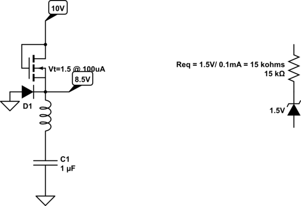
All FETs are defined in datasheets with Vgs=Vds = \$V_{gs_{TH}}\$ a.k.a Vt as the threshold voltage at some tiny current like 100 uA.

This is what your circuit looks like in this question.

schematic

simulate this circuit – Schematic created using CircuitLab

Thus your C would charge up to 8.5V = 10V - Vt in milliseconds instead of microseconds.

Due to the square law in reducing RdsOn, for logic level FETs you need 2x Vt and older standard FETs with Vt= 2 to 4V with 2.5 to 3x Vt to achieve rated RdsOn.

\$\endgroup\$

Your Answer

By clicking “Post Your Answer”, you agree to our terms of service and acknowledge you have read our privacy policy.

Not the answer you're looking for? Browse other questions tagged or ask your own question.