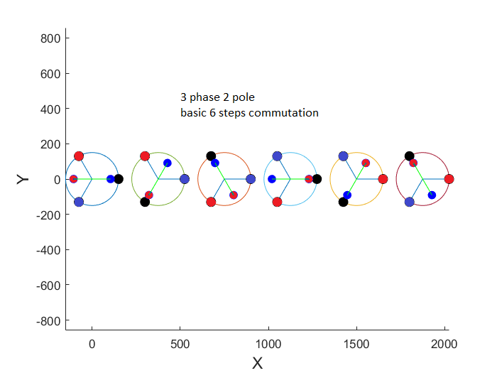
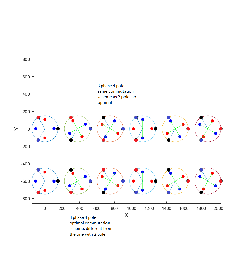
I am trying to design a three phase 4 pole motor, control with six-step. My problem appears when I draw the commutation to try to see how everything work. First, with a basic three phase 2 pole, there is no problemand the switching sequence seems logical to me. But next, when I move to a 4 pole motor, with the same commutation scheme, only doubling the frequency, the commutation I get is out of phase compare to what it should be. I added image below for you to understand my problem. I can't find any litterature about this problem and I am really stuck. The problem also appears if you try on a five phase motor, and higher number of poles also changes the back EMF, and a lot of parameters. Am I getting something wrong ?
-
\$\begingroup\$ What do you mean by optimal and should be? \$\endgroup\$– Mister MystèreCommented May 18, 2022 at 10:27
-
\$\begingroup\$ If you want to generate torque, you have to comutate coil in order to attract and repel the magnet correctly. In my case, some coil are generating positive torque but other are generating negative torque. At the end, the torque is not optimal. \$\endgroup\$– CyrilCommented May 18, 2022 at 15:04
1 Answer
The problem you have with 2 pole pairs is that the construction of the rotor and the stator are such that for every North pulled by the stator there is a South which is, instead of 180° from that North and therefore well clear of the stator's Souths, close to and on the wrong side of a stator South. So it's normal the commutation scheme has to change.
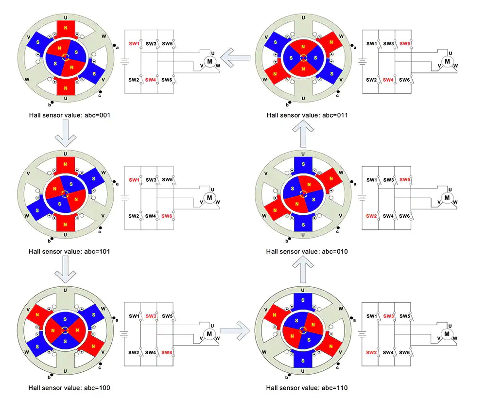
Teeth/slots are different from phases. If you want to adapt the stator consutruction to the rotor you could build your motor based on 3 phase, 6 slots, 2 pole pairs. In this configuration, for every pole pulled the opposite poles get out-of-alignment with the next winding to be energised such that the rotor is turned in the opposite direction as the stator field rotation.
(Image source: Monolithic Power Systems - Brushless DC Motor Fundamentals, Application Note AN047, Prepared by Jian Zhao/Yangwei Yu)
You should add a brief description of how you obtained your figures: it looks like the rotor position is forced from frame to frame, whereas it could be (and more logically for me) the position of the rotor resulting from the previous state. The legend is also missing, but I assume red means north and blue means south. Just something to think about next time.
-
\$\begingroup\$ Thank you for your answer. To be a little bit more precise, my scheme is made by rotating the magnet 1 step at a time. In a 3 phase motor, we use 6 step commutation, so there are 6 image. I am actually trying to go beyond three phase, 5, 7 or even 9 and my goal is to generalize a bit. My problem is that in litterature, the only thing changing by adding pole is the frequency of commutation, which i perfectly understand. But here is the problem, if you add pole, the commutation has to change (as you say and I agree), but there is no info anywhere about how to change it. \$\endgroup\$– CyrilCommented May 19, 2022 at 11:51


