I am designing a 4-Layer 0.5mm thickness PCB.
The outline is rather small which introduces some problems with panelizing the PCB. As I am a novice regarding these topics I would like to ask for help.
My PCB house does not have any recommendations on this topic. In their opinion "it can work, but I should try it" - the burden of low-volume customers.
My requirements:
- The PCB must be a "break-away" style within the panel.
- There must be test signals routed on the inner two layers for production testing.
- Pogo-pins cannot be used on the PCB directly as there is no room for pads and I would like to avoid micro-probes (sub 0.5mm landing pads.)
- The IC packages/passives must not be harmed during manual and automated depanelization.
- The top and bottom edge (see image) must be routed.
- V-dcoring is not possible due to PCB-thickness.
- Neither buried nor blind vias are possible.
- The "mouse-bites" must not extend beyond the PCB-outline if possible.
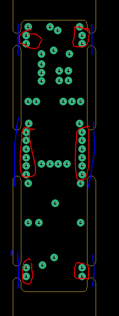
My current design is attached below:
The blue lines indicate the break-away lines. The yellow lines are the board outline and the encircled (red) vias are used for test-signals.
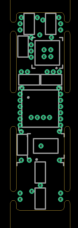
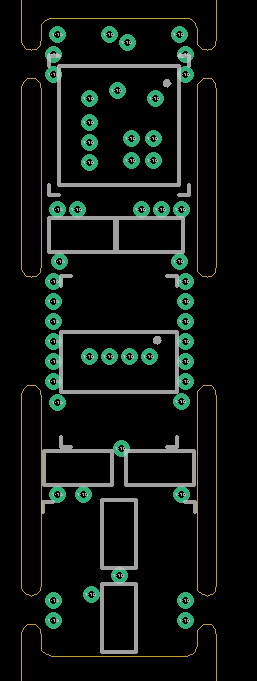
The white lines do indicate the component outlines (0.25mm to component edge)
My Concerns:
- I am absolutely concerned that the components/the solder joints on the center ICs (top and bottom) will be damaged during depanelization.
- I am concerned, that the test-signal vias (0.4mm diameter, 0.2mm drill) on TOP/BOT will get ripped off due to their proximity to the board-edge - they are used "for the mousebites" as it is necessary to route signals across the break-away tab on the inner layers.
- I am concerned that the components (especially the 0402s) will crack during depanelization due to their proximity and the rather "stiff" break-away tabs. Therefore I project a reduced yield.
- I think that the mousebite vias are not far enough on the inside of the PCB outline and therefore the PCB outline will be violated after depanelization.
- I fear the possibility that the inner layer test signals will be "pulled out" during depanelization. Therefore, the signals will be broken and unusable within the perimeter of the actual PCB.
My questions:
As I want to get the design "some-what right" before ordering test-panels I appreciate any help.
- Are there cost-effective options available to avoid the routing of test-signals without adding any board-space?
- Is the "pulling" out of inner layer traces a problem?
- Is the proximity of the ICs/passives to the mousebites a problem?
- If so, how to avoid it in such a space constraint application? (See 1.)
- How are these problems/applications handled by professionals? What kinds of solutions do they apply?
PUSH


