0
\$\begingroup\$

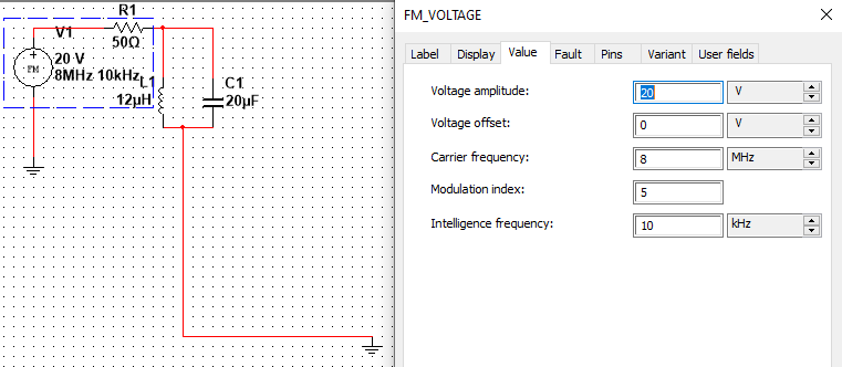
I have the circuit below which consists of a series resistor followed by a parallel LC circuit:

enter image description here

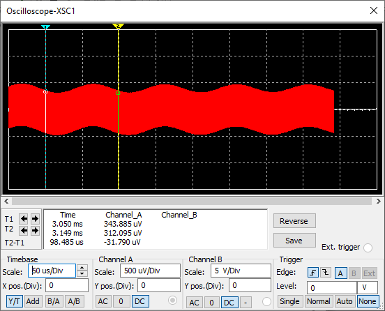
It produces this output waveform:

enter image description here

From the simulation, I know the waveform has a frequency of 10Khz since the period of 1 complete cycle almost 100 microseconds. The parallel LC circuit has a stopband of 10Khz which is to capture the 10Khz signal. Since the carrier id 8MHz, the parallel LC circuit acts a near short circuit to ground so that only a very small constant amplitude of thr carrier signal remains. In FM modulation, there is a series of frequencies in the waveform. The 50ohm and the parallel circuit parallel LC circuit form a voltage divider circuit according to the formula:

$$V_{out}=V_{in}\frac{z}{z+50}$$

Where z is frequency dependent then voltage output also varies with time according to the potential divider formula. The voltage output is the filtered carrier amplitude+Vout of the stopband. This explains why the output voltage is changing with time.

For the second part, I can't find the reason why the amplitude decreases after the simulation is run for a period of time:

enter image description here

Please help to explain or give some hint on this.

\$\endgroup\$
1
  • \$\begingroup\$ Did you try to get a bode plot? It tells a lot about what's happening. \$\endgroup\$ Commented May 21, 2022 at 7:50

2 Answers 2

1
\$\begingroup\$

As @Rohat Kılıç suggested, here is the AC analysis which gives some pieces of information.

You should now search for finding the "time" function.

Write the function in terms of "s", then use the "Laplace Invert" operator.
It will be a "little" more complicated.

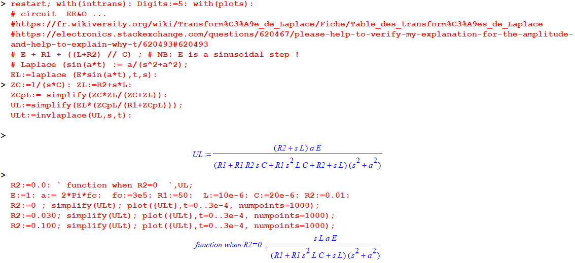
Here is a Maple sheet for transient.
NB:
1- Carrier frequency has been changed to 1e5 to see something (the carrier), not too "black" ...
2- R2 (0, 0.030, and 0.100 Ohm), to see the change of damping (exponential term), is the serial resistor with the inductor.

enter image description here

And the results ... (see the change of "damping" and time equations).

enter image description here

For the steady-state ... I will do a simulation, which is easier, sometimes.

Searching first for the "transfer" function (AC analysis) of the circuit:

enter image description here

Now, the use of this function.

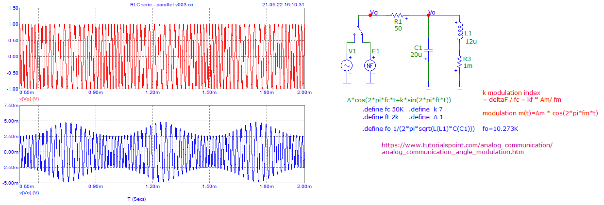
The generator is a device delivering a frequency modulated wave with an 8 MHz carrier.

This carrier is, frequency speaking, on the response curve to the right of the resonance which occurs at 10 kHz.
We, therefore, find ourselves in the case of a transmission of the FM on a filter edge at -20 dB/decade.

When the frequency of the FM signal varies, the filter delivers at its output a voltage which decreases when the frequency increases.

An output signal is therefore obtained, the amplitude of which varies at the rate of the modulating frequency.

It will therefore suffice, in a simplistic way, to demodulate (as in AM) by a classic peak detection.

I chose the frequencies to make it as visible as possible and easy to simulate and not too long.
Do you see where the frequency is the highest and the lowest?

enter image description here

\$\endgroup\$
4
  • \$\begingroup\$ Yes, spotted the highest and lowest frequency. I changed the voltage parameter of my multisim simulation accordingly to your parameter and can see clearly frequency variation at the envelope. Thank for your explanation on the amplitude section. \$\endgroup\$
    – chuackt
    Commented May 21, 2022 at 17:27
  • \$\begingroup\$ Also, during startup of the circuit, the amplitude decrease exponentially before reached a stable state. Is this phenomena have to do with the 3 state for RLC circuit which is underdamped, overdamped and critically damped? \$\endgroup\$
    – chuackt
    Commented May 21, 2022 at 17:30
  • \$\begingroup\$ Yes... But during the startup, it is a bit complicated because we have an RLC circuit that is supplied with a frequency wave modulation (modulation index is important). It is thus not a simple excitation as a step pulse or a continuous wave at only one frequency. I don't remember if a "Laplace function" for an FM wave exists (I think yes, but I did not use such a function very often, perhaps in my youngest time, a long time ago ... :-). I will search and add it into my answer. \$\endgroup\$
    – Antonio51
    Commented May 21, 2022 at 18:48
  • \$\begingroup\$ However, In the first approximation and for the starting phenomena (if index modulation is very low), one can use a "continuous wave" at the carrier frequency applied to the RLC circuit as usual. \$\endgroup\$
    – Antonio51
    Commented May 21, 2022 at 18:48
0
\$\begingroup\$

I believe there are transients involved. These are exponential decays that are added to the voltage due to the switching. These transients decay with time reducing the maximum voltage attained.

\$\endgroup\$

Your Answer

By clicking “Post Your Answer”, you agree to our terms of service and acknowledge you have read our privacy policy.

Not the answer you're looking for? Browse other questions tagged or ask your own question.