0
\$\begingroup\$

For KiCad to detect the +5V and GND parts of a schematic, I assume the power component symbols have to be attached.

How does this work when the power comes in via a terminal?

In the image below, I have had to attach additional GND and +5V symbols to the net, behind the terminal, so tools like the copper fill tool can recognise the different parts of the net.

enter image description here

This (probably naively) feels a little like adding extra connectors that aren't really there. Is there a better way of indicating power is supplied through the terminal or is this the correct approach?

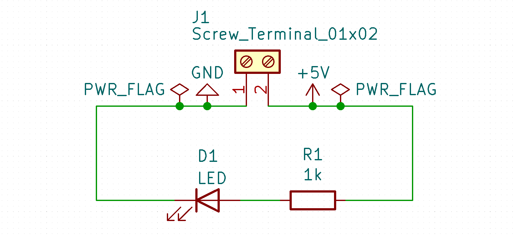
\$\endgroup\$
2
  • 1
    \$\begingroup\$ This is the correct approach. However, a style issue: GND should point downward and be below all positive voltages. NOTE: I don't use kicad but all schematic tools work the same, more or less. \$\endgroup\$
    – user57037
    Commented May 31, 2022 at 5:12
  • \$\begingroup\$ All schematic tools create a "netlist." A netlist is a list of nodes. Each node is a list of pins or pads which belong to the node and must be connected together electrically. Each node may have a name assigned by the person who draws the schematic (you). If no name is assigned to a node, then the schematic tool will probably assign one sequentially or randomly or some such. When you put the +5V label on there, you are naming the node. It seems that Kicad supports node properties such as PWR_FLAG also. Without a label, Kicad wouldn't know that the node has any special name or properties. \$\endgroup\$
    – user57037
    Commented May 31, 2022 at 5:25

2 Answers 2

1
\$\begingroup\$

For KiCad to detect the +5V and GND parts of a schematic, I assume the power component symbols have to be attached.

KiCAD recognizes the "+5V" and "GND" labels but, if you don't specify that those nets are driven from somewhere (you don't need to tell KiCAD where), KiCAD will produce a warning when performing an electrical rules check.

So, adding the PWR_FLAGs is a means of telling KiCAD that it doesn't need to make a warning message when checking those nets/lines.

How does this work when the power comes in via a terminal?

KiCAD doesn't recognize a terminal as a source for the power on a net so, you still need to add the PWR_FLAGs.

This (probably naively) feels a little like adding extra connectors that aren't really there. Is there a better way of indicating power is supplied through the terminal or is this the correct approach?

When I first used KiCAD I hated PWR_FLAGs thinking them unnecessary but, they are what they are; just a method of preventing warnings when performing electrical rule checks.

\$\endgroup\$
0
\$\begingroup\$

In Kicad power signals (the part from the 'power' library, they are special) are global nets so they are tied in the schematic on each sheet. If you are getting them from the outside just connect the terminal, it doesn't really care about that.

As for the pwr_flag it only exist to keep the DRC happy if you are using it but personally if found it completely useless for modern designs: the pin types matrix would have been OK in the '80 with all the logic power tied to a single +5V rail but these days if you only put a ferrite bead in between it pops up with a pin not powered.

\$\endgroup\$

Your Answer

By clicking “Post Your Answer”, you agree to our terms of service and acknowledge you have read our privacy policy.

Not the answer you're looking for? Browse other questions tagged or ask your own question.