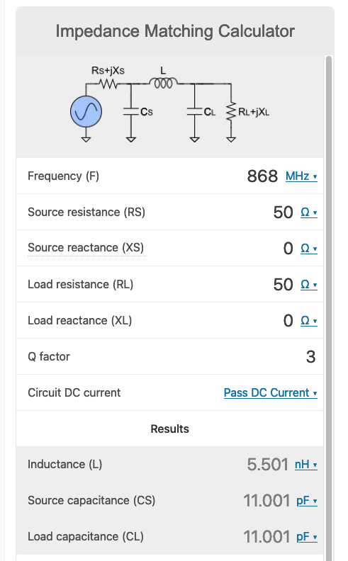
This is how i've placed my Frequency (F=868) reference, my Source
resistance \$\color{red}{\text{(RS=50)}}\$ and my Load Resistance \$\color{red}{\text{(RL=50)}}\$
Your source and load impedances are identical so, you have no need to match them. The pi network will give you some filtering benefits but that's a different question.
The Q factor can be 3? Must it be higher? Lower? Is there a "rule of
thumb?"
Here's where there's a bit of controversy as to what Q factor actually means. This document (entitled Quality Factor, Bandwidth, and Harmonic Attenuation of Pi Networks) discusses what the so-called Q factor is in pi filters and concludes that it can mean different things to different people.
Significantly, the on-line calculators that invoke Q factor as a parameter don't appear to justify what it means or how to use it. Think about a pi filter of equal input and output impedance; the circuit gain has to be unity hence, Q factor should be unity basically because: -
$$Q = A_V = \sqrt{\dfrac{R_L}{R_{IN}}}$$
On my basic website I don't use Q factor because of the ambiguity stated above. I derive the pi network as two back-to-back L-pads like this: -

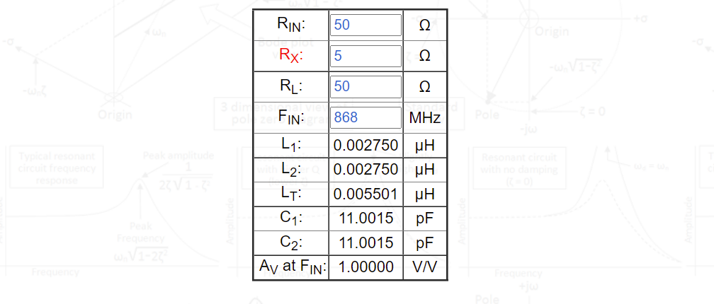
\$R_X\$ would be the output impedance of the left hand L-pad or the input impedance of the right-hand L-pad. Of course, when placed back-to-back they fully interlock as matching impedances AND, \$R_X\$ is unambiguous in that respect. For instance, if I use my calculator at 868 MHz I get the same results as the calculator you used when \$R_X\$ is 5 Ω: -

And, if I vary \$R_X\$ you can see it is peakier in the response as \$R_X\$ gets lower: -

Incidentally, the graph above is when \$R_{IN}\$ = 50 Ω and \$R_L\$ = 300 Ω. So, decide yourself whether you want to use Q or want to use \$R_X\$. As a last resort, you can always simulate the circuit to look at the frequency response.


