2
\$\begingroup\$

I am new to arduino and electronics in general but I need some help on a project I am working on. Essentially I want to be able to control the state (on/off) and direction of two linear actuators that are really just DC motors.

It seems easy but the problem is that the linear actuators are each 12VDC and consume 10 amps of current at full load. I bought a 25A external power supply because obviously the arduino microcontroller cannot not provide that much current.

I saw something about using an H bridge to control each motor's direction and then I read something about using a relay that acts as an electromechanical switch to draw current from the power supply. Can someone help me out or draw me a circuit diagram of what this looks like so I could be able to put it together? I would love to know how all of this works and I know it is probably challenging to beging electronics with but I am willing to learn as much as I can about this stuff.

\$\endgroup\$

3 Answers 3

1
\$\begingroup\$

You can use any 12v speed controller that accepts a PWM signal. There are many such controllers available. Check eBay and google.

What you will be doing is using the PWM signal from the arduino to control a speed controller that is "regulating" the voltage to a motor. This way the power source for the motor is completely independent from the arduino.

Personally I have experience using Talun and Jaguar speed controllers. Those are both very expensive, but they will give you an idea of where to start looking.

Here is what I would search for on eBay

\$\endgroup\$
1
\$\begingroup\$

Take a look at the Pololu High-Power Motor Driver 18v15. It would seem to meet (and even exceed) your needs. I purchased one of these last week and it should arrive tomorrow. I'll edit this answer with my review.

3/27/13

Got it in the mail late yesterday. Assembled it tonight. Will be testing it out tomorrow.

4/7/13

My time with the switch was short yet incredibly productive. The boat in which the switch was placed eventually sunk taking a GPS, XBee, Arduino, and the switch with it. The switch was really easy to get up and running with. The soldering was quick and the provided capacitor worked nicely for my purposes. My battery's positive terminal connected to the V+ header and the negative terminal connected to the GND header. The motor's leads connected to the OUTA and OUTB headers. The polarity doesn't matter on those two headers as the device is capable of switching it.

On the logic side I connected the Arduino's GND pin to the switch's GND header. I didn't make use of the FF1 and FF2 fault flag indicators but reading them is as simple as a digitalRead once they're connected to the Arduino. The RESET pin is really easy to use. Just use digitalWrite(resetPin, LOW); to put the board into sleep mode (this also clears any faults). Bring it back up to high to resume normal operation.

There are two ways to operate the board but I'll only discuss the one I used which I believe is simpler. The DIR pin needs to be considered digital. So you set it up just like you would any normal digital output pin on the Arduino. You pull the pin HIGH for one direction and LOW for the opposite direction. This effectively reverses the polarity on the OUTA and OUTB headers. The PWM pin needs to be connected to a PWM-supported pin on the Arduino. On the Arduino Uno these pins are 3, 5, 6, 9, 10, and 11. Make certain that the pin that you choose is not being obstructed by a timer interrupt. Controlling the speed of the motor is as easy as using analogWrite on the pin with a number from 0 (stopped) to 255 (full speed). The map function will be really useful here. You can use it to take any sane range and convert it to the range you need (in this case 0-255). I used it to take 0-255 down to 0-100 to create a thrust percentage I could display but in that case I could have just divided the the number by 2.55. ;) Check out this commit on GitHub to see how I implemented it. Contrary to that commit, you do not need to use pinMode on the PWM pin.

The only "issue" I ran into with the board was that when running the motor it would create an audible tone depending on the speed. At full speed it wasn't noticeable but at lower speeds you could really tell. I didn't fix this issue before the boat sank but I'm told it can be resolved by using the Arduino PWM Frequency Library.

I hope this helps you and have fun with the motor driver. I would definitely buy another if a situation called for it. Definitely take a look at Pololu's product page for a very detailed explanation of the entire chipset.

\$\endgroup\$
4
  • \$\begingroup\$ I actually just saw this response and I ordered one just like that from polulu but i had to get a dual motor driver because i am controlling two linear actuators (acting as DC motors). did it work out well for you? I might be a little confused by the pin connection so I will get back to you if i need help \$\endgroup\$ Commented Mar 31, 2013 at 20:45
  • \$\begingroup\$ I haven't had the opportunity to hook it up but it seems easy enough. V+ and GND and then a pin for direction and a pin for speed. \$\endgroup\$
    – Kevin Mark
    Commented Mar 31, 2013 at 23:01
  • \$\begingroup\$ Do you know which pin of the H bridge goes to which DC motor terminal. For example, does M1A go to positive and M1B go to negative, or vice versa? \$\endgroup\$ Commented Apr 6, 2013 at 17:15
  • \$\begingroup\$ @GregHarrington I'll be updating my post today. It does not matter if OUTA or OUTB is connected to the positive or negative leads on the motor. Brushed DC motors should be able to accept current in either polarity. That's how you reverse the direction! The digital DIR pin will reverse the polarity of OUTA and OUTB. \$\endgroup\$
    – Kevin Mark
    Commented Apr 7, 2013 at 22:00
0
\$\begingroup\$

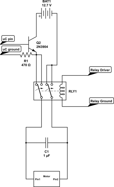
It may be easier and cheaper if you used a DPDT relay to change the direction of the motor. Here is a schematic of what I mean:

schematic

simulate this circuit – Schematic created using CircuitLab

The microcontroller pin you use on the power transistor (labeled Q2 in the schematic) will allow current to flow through the relay, the direction the current moves through the motor is dependant on the state of the relay. I have used this circuit for many projects due to its simplicity, cost, and the inherent robustness of relays.

*Quick note the transistor used in the schematic is not capable of handling 10 amps of current. I have had good fortune with the tip142 darlington pair transistor, the data sheet says it can handle 10 amps continuous current. Datasheet: http://www.alldatasheet.com/datasheet-pdf/pdf/25370/STMICROELECTRONICS/TIP142.html

*Make sure the capacitor you use on the motor can handle many hundreds of volts

*The relay coil will need something to drive it, that can take a few configurations depending on the relay used.

*As for cost, the relay can run up to four or five bucks, same for the transistor.

\$\endgroup\$

Your Answer

By clicking “Post Your Answer”, you agree to our terms of service and acknowledge you have read our privacy policy.

Not the answer you're looking for? Browse other questions tagged or ask your own question.