0
\$\begingroup\$

I'm building a circuit from discrete components to run a gate drive transformer to drive the gates of a full bridge DC-DC converter.

Before I set the drive frequency and wind the power transformer, I wanted to know if the actual operating frequency is the sum of the frequency of both pulse trains or is it the just the one.

I think I remember someone on this forum telling me that it was double, years ago and I watched a lecture on YouTube where I believe the professor said the same thing, around the same time.

I'm using an EE55, PC40 material. I think 100 kHz is the limit at .25T, which may be pushing it because .5T was Bsat at room temp.

I read in a book that at 100 kHz, Bmax should be set to about 50 percent of the material’s saturation flux density. At 500 kHz, the Bmax should be no more than 25 percent of Bsat, and at 1 MHz, the Bmax should be about 10 percent of Bsat. However the book has no mention of what I'm asking because the book assumes the use of a dedicated IC.

Should I set the pulse train frequency to 50 or 100 kHz?

Also any advice on the operating frequency of that ferrite would be appreciated.

\$\endgroup\$
1
  • 2
    \$\begingroup\$ Can you add diagrams/plots of what and where you consider "pulse trains" and "drive frequency"? \$\endgroup\$ Commented Jun 28, 2022 at 4:04

1 Answer 1

0
\$\begingroup\$

The best is to run a quick simulation of your full-bridge converter. Below is a typical full-bridge converter with power switches diagonally operated from a 200-kHz internal clock. However, because of the logic arrangement, the frequency on the gates is 100 kHz (10 µs):

enter image description here

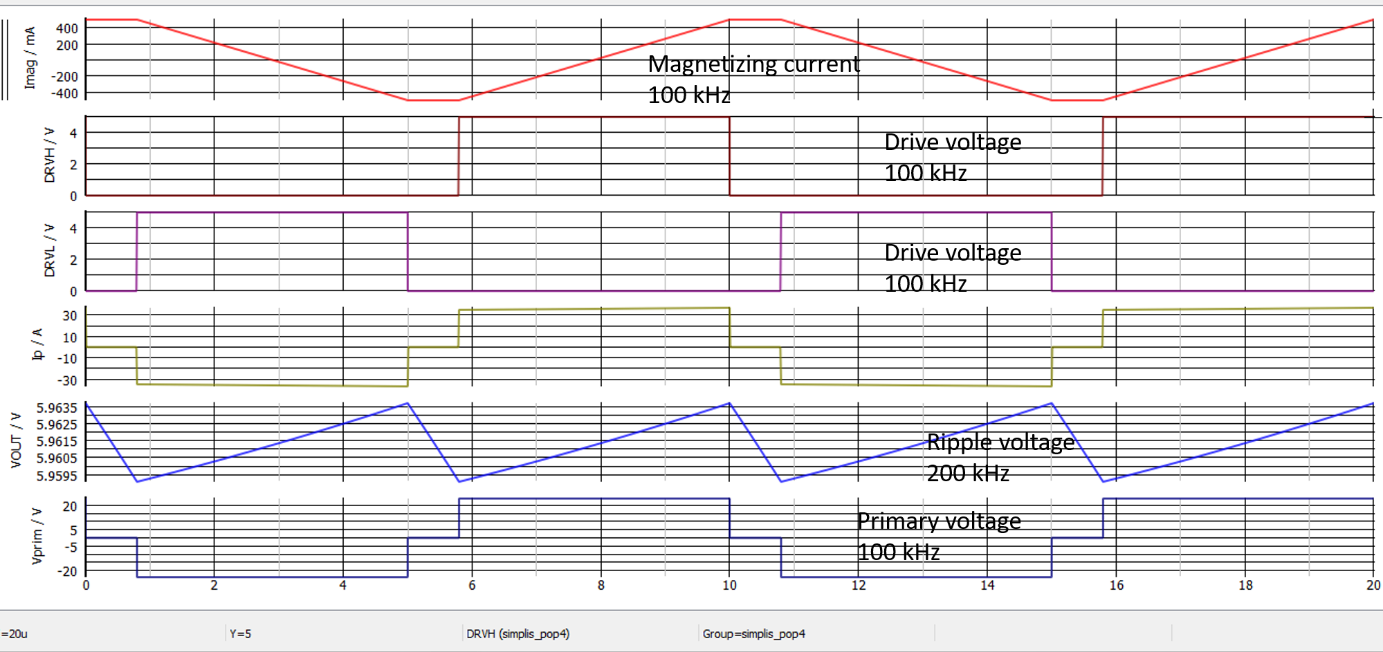
If you run the simulation, SIMPLIS will give you the steady-state operating waveforms and the ac response in a fraction of second:

enter image description here

These results were obtained using one of the 60+ free ready-made templates that I recently released with my last book on transfer functions. You can download them from my webpage, they work for most of them - the full-bridge shown in the example certainly does - with the free demo version.

What matters for the core losses is the magnetizing current which is also at 100 kHz as shown on the graph. The output ripple, though, is well at 200 kHz as you mentioned in your post.

Now regarding core losses, I recommend you look at some of the videos posted by Ray Ridley on his YouTube channel as they contain useful information on this topic.

\$\endgroup\$
2
  • \$\begingroup\$ Thanks for the answer and the link to Ray Ridley. I learned a lot about core loss and something I've been interested in, zero voltage switching. \$\endgroup\$ Commented Jul 2, 2022 at 3:13
  • \$\begingroup\$ With pleasure! Happy if these information could help : ) \$\endgroup\$ Commented Jul 2, 2022 at 15:18

Your Answer

By clicking “Post Your Answer”, you agree to our terms of service and acknowledge you have read our privacy policy.

Not the answer you're looking for? Browse other questions tagged or ask your own question.