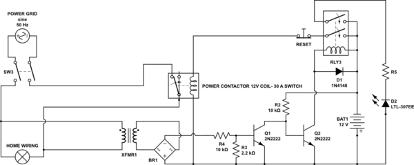
Firstly, you are playing with mains electricity. Everything I suggest here is contingent upon you knowing that it could kill you, or someone else.
Secondly, altering mains-connected wiring may lay you open to prosecution in some regions, and doing so without precisely following the codes in your jurisdiction could invalidate your house insurance in the event of any claim for any reason. If you get anything wrong, that's on you.
By convention, current is defined in electronics to be a flow of positive charges. We don't talk about electron flow, we consider the positive terminal of a voltage source (like battery BAT1 or rectifier BR1) to be where positive charges, come out, and flow around to re-enter at the negative terminal.
Therefore BAT1 and BR1 are upside down in your schematic. From here on I will assume you've corrected that problem, and will talk as if they were the correct way round, with positive at the top.
Mains sensing
The section of circuit consisting of XFMR1, BR1, R4 and R3 produces a series of positive voltage pulses, not a constant DC potential:
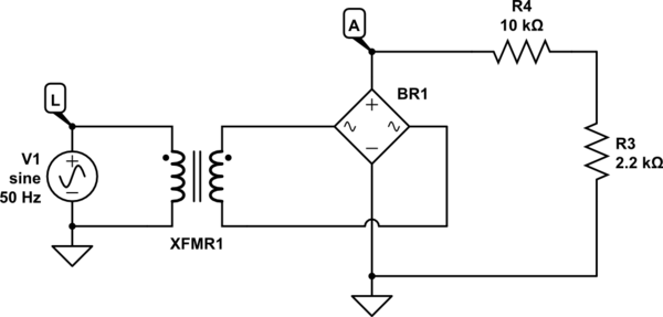
simulate this circuit – Schematic created using CircuitLab
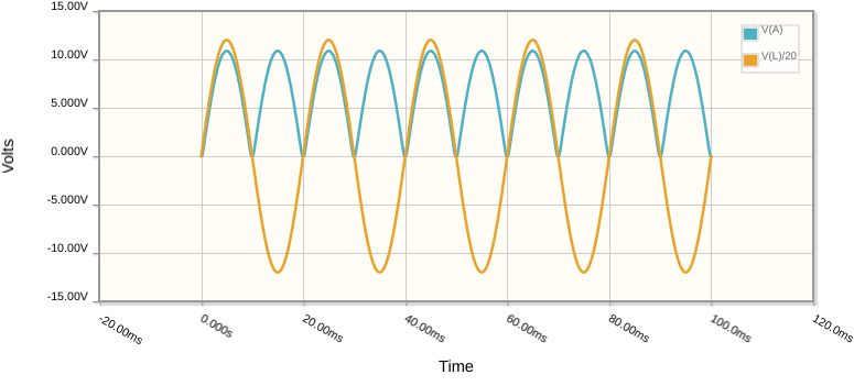
I've scaled down the mains input voltage (orange) by a factor of 20 here, so it doesn't dwarf the output (blue). The point being illustrated in that graph is that the rectifier simply flips the negative portions of the cycle upside down to become positive, and the result is an output consisting of a series of positive pulses of twice the frequency of the input waveform. Output frequency would be 100Hz in Europe, or 120Hz in North America.
Your transistor Q1 will be switched on and off 100 times per second; I believe your intention was to switch Q1 on when mains electricity is present, and to switch it off only during a blackout. To achieve that, we must "smooth" the potential at A, so that it remains high during the whole cycle, and only drops low after the cycles have disappeared, which is easy to do with the addition of a single capacitor:
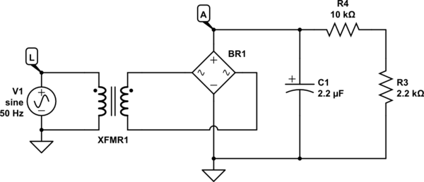
simulate this circuit
The potentials at L and A now look like this, over time:

Node A slowly decays to zero, after mains input is removed, but while mains is present it permanently remains high enough to switch on a transistor. The amount by which the potential at A "droops" between pulses, and the rate at which it decays following mains blackout, is related to the product of C1 and R4. If you wish to reduce droop, for example, increase C1 or R4). That will slow the decay, but will also increase the time it takes to "trigger" the cut-off response.
Your use of R4 and R3 is correct, but the values you chose would tend to attenuate the "black-out" signal quite severely. R4 and R3 form a voltage divider, dividing by about 5.5. This might cause Q1 to switch off a little prematurely. It might be too sensitive to fluctuations in mains voltage average. I would suggest a more conservative attentuation, something like ÷2. If you used two resistors of 10kΩ, that would work.
Single Relay
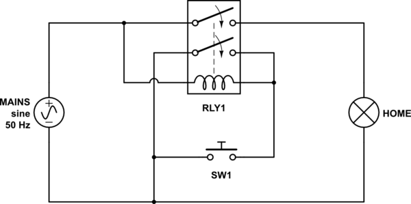
I know you said that you want the power relay coil to remain un-energised while mains power is present, but if you are willing to sacrifice that requirement, then your project could be implemented with a single DPST relay, and momentary switch:
simulate this circuit
Notice how SW1 and one of the relay switches are connected in parallel. Closing either one will energise the coil. When power is first applied, nothing happens, because neither switch is closed.
However, if you actuate the relay by pressing SW1, you also close the relay contacts. Even if you release the switch, the relay will keep its own coil powered. It is then "latched" on until power is removed, at which point the relay will de-energise, and return to the off state.
Of course this relay will need to have a high voltage AC coil.
I just noticed that user emrys57 posted an answer about a "no-voltage release switch". I believe such a device uses a similar approach.
Just for fun - emergency stop
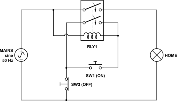
Many emergency stop switches (on power tools) work this way, except in addition to the "power on" switch, they also have a button to cut off relay coil current:
simulate this circuit
Hybrid system with 12V DC relay coil
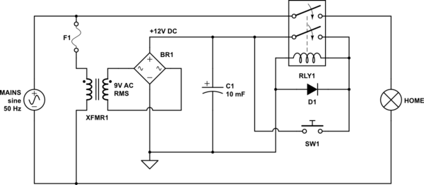
If you've set your heart on using a relay with a low voltage DC coil, nothing is stopping you from employing this "self-latching" relay trick there too:
simulate this circuit
