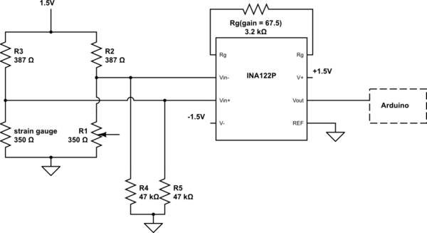
I'm building a circuit to measure signal out of a wheatstone bridge for strain gauge.
here is the schematic:

simulate this circuit – Schematic created using CircuitLab I applied +-1.5V with digital power supply and measured the output with Arduino. For the bridge circuit, I don't have 350 ohm resistors which have the same resistance as the strain gauge so I used a 0-500 ohm potentiometer to set up the 350 ohm. Reference is connected to ground and those two 47k ohm resistors are for bias, which I made exactly like what is shown in the datasheet.
datasheet for the INA: https://www.ti.com/lit/ds/symlink/ina122.pdf
Now there are some issues:
1. I tried to balance the bridge as much as I can and I can measure around 0.75V(with multimeter) at both inputs so that the output should be 0V. However the output shows around 1.4V. I think it's not saturated yet because I can get exactly 1.5V(measured with multimeter) at the output when I decrease the potentiometer resistance a little.
2. I measured all the voltage above with multimeter and also connect the output to Arduino. The reading on Arduino, however, swings periodically between 1.2V and 1.5V while the reading of output on the multimeter is constantly 1.4V.

