1
\$\begingroup\$

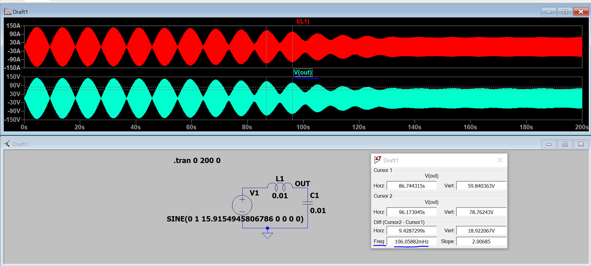
The following is an LC circuit excited at resonant frequency 15.915Hz (L=10mH, C=10mF.)

I would expect the output to have only the resonant frequency (constantly increasing in amplitude) since the AC source and the natural response are of the same frequency.

enter image description here

  1. Why is there an underlying frequency of 100mHz?

  2. Why is the amplitude not increasing continuously?

Both L and C are defined to have zero resistance (ESR.)

\$\endgroup\$
1
  • \$\begingroup\$ The behavior is logical. It is the response to a "step sinusoidal" input ... The parameters of the simulator have nothing to do with this circuit. Just the difference of the natural frequency and the frequency input. \$\endgroup\$
    – Antonio51
    Commented Aug 11 at 12:43

2 Answers 2

4
\$\begingroup\$

Your circuit has no damping (except the Rser=1m default parasitic of the inductor, or the Rpar=1/Gmin for the capacitor, if added), so what you see is not the "real" result. Since there is (virtually) no damping then there can be no damped oscillation, so the output should rise to infinity and, possibly, beyond. To correct the output you need to impose a tighter timestep. Here is how the output looks like for an increasing timestep of 1 s (no effect since it's less than 1/1024 points, by default), then for 1 ms, and then for 10 us (1 us will not be an improvement over 10 us):
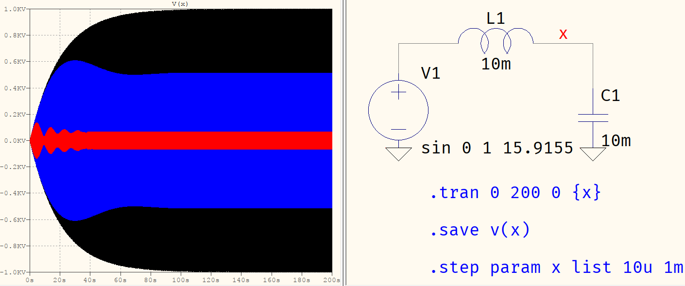
needs tighter timestep

If it stops at 1 kV amplitude it's because of the Rser=1m. If you set it to zero, it will do what you expect it to do. The reason has to do with how the SPICE engines calculate their timesteps and how very simple, linear circuits, such as this one, can influence it. TLDR: if it's simple and fast, the timestep shall not be constrained. Of course, the simulator tries to do what it can with the given input, so GIGO applies (which is your case: ideal voltage source, "pure" LC).

\$\endgroup\$
2
  • 1
    \$\begingroup\$ You can also decrease the Reltol setting to something like 1e-6 or even 1e-10, the results don't get much better after 1e-6 though. \$\endgroup\$
    – Arsenal
    Commented Jul 19, 2022 at 11:30
  • \$\begingroup\$ @Arsenal True but, to this day, I'm still not sure whether the tighter timestep or the *tol settings have the more adverse effect on the simulation time. The point remains that what OP wants is a text-book analysis of an ideal circuit, which the numerical side of SPICE does not, and cannot agree with, given numerical precision. \$\endgroup\$ Commented Jul 19, 2022 at 14:05
1
\$\begingroup\$

There may be something hidden with your voltage source if you are getting that result. Possibly LTSpice has created a little bit of series resistance or current limiting because, no-way would the output settle down to an 80 volt peak sinewave without this damping being present. Neither would the perturbations remain at a fairly constant amplitude up to the 50 second point in the plot.

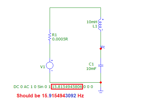
Additionally, your excitation frequency is miscalculated at around the 7th decimal place but even that wouldn't cause the perturbations you see. To get what you see, the excitation frequency would need to be out by about 0.1 Hz so, double check that you didn't use 15.815 Hz instead of 15.915 Hz. In Micro-cap, to get anything like the same response as yours, I would need to drive the tuned circuit with a 0.1 Hz error and have series resistance of about 0.0005 Ω: -

enter image description here

Circuit simulated: -

enter image description here

But, if I discard the series damping resistor and slight error in the excitation frequency, the output waveform will do this (as expected): -

enter image description here

Notice that the waveform has peaked at +/- 10 kV after 200 seconds and, will continue in this fashion theoretically.

\$\endgroup\$
5
  • \$\begingroup\$ Depending on mode, the damping may also be numerical convergence error. High Q networks are notoriously hard to simulate. Unfortunately it's also the case LTSpice may insert ESRs when the user may not intend them to be there (i.e. default values). \$\endgroup\$ Commented Jul 19, 2022 at 13:54
  • \$\begingroup\$ @TimWilliams OP has stated that the series resistances are set to zero. While in LTspice setting something to zero might mean using the default value (even if it's non-zero), for inductors, Rser=0 means zero series resistance. \$\endgroup\$ Commented Jul 19, 2022 at 14:12
  • \$\begingroup\$ @aconcernedcitizen they stated L and C, but not V1 (at present, anyway) \$\endgroup\$ Commented Jul 19, 2022 at 14:15
  • \$\begingroup\$ @TimWilliams That's true, but the voltage source has a default (machine precision) zero resistance. In order for it to have any value, it must be explicitely set. \$\endgroup\$ Commented Jul 19, 2022 at 14:17
  • 1
    \$\begingroup\$ @aconcernedcitizen Ah, got it. \$\endgroup\$ Commented Jul 19, 2022 at 14:19

Your Answer

By clicking “Post Your Answer”, you agree to our terms of service and acknowledge you have read our privacy policy.

Not the answer you're looking for? Browse other questions tagged or ask your own question.