1
\$\begingroup\$

The problem is only in the input stage of the op-amp.

Edited: removed reference to "eddy-current" and changed to "reluctance".

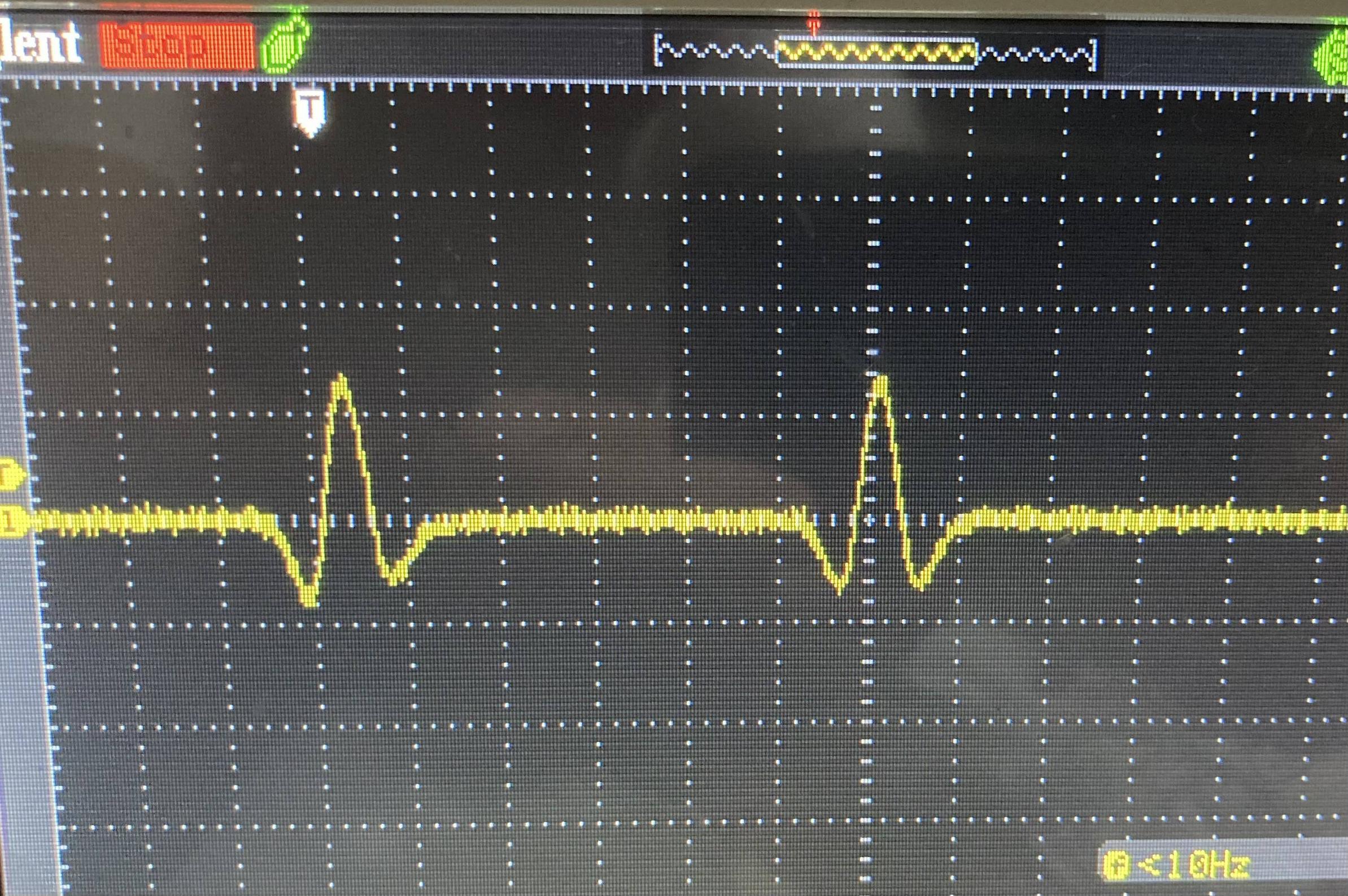
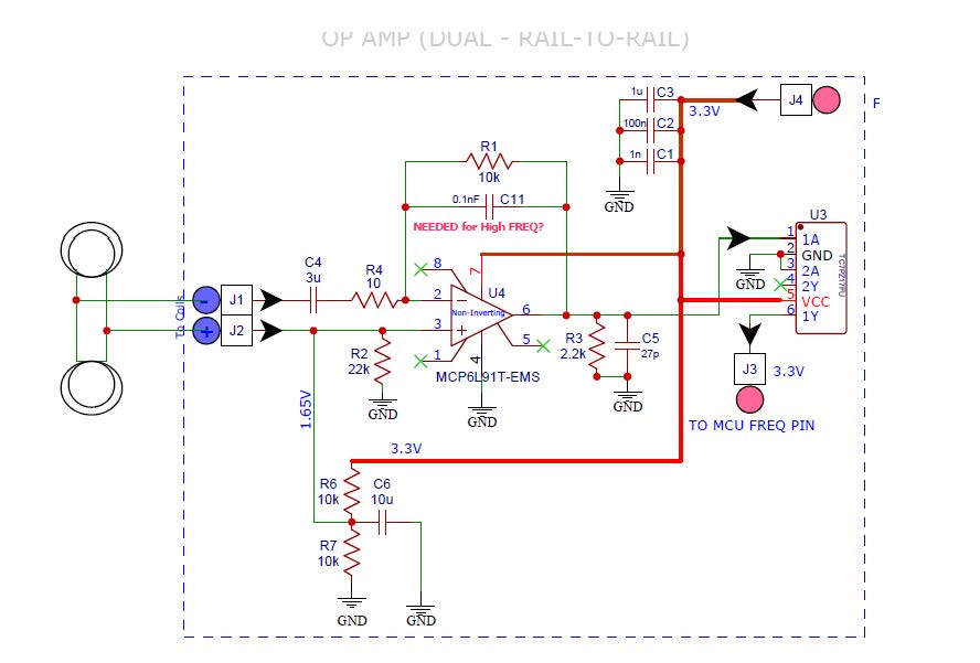
The reluctance-current is generated from two coils by ferrous movement passing through them. The coils are 10 ohm each with 0.254 mH. The current coming out of them is a sine wave that goes positive and negative. The circuit works 95% of the time as it is, but at times it seems that the difference between the two op-amp inputs (2 and 3) is not enough to result in an output.

On the bench, if I simulate things and feed a positive 3 V pulse into J1 going to Pin 2 of the op-amp and also ground J2 (going to pin 3) then it works 100% of the time. Of course, in real life the current is not only positive.

I suspect that when the positive and negative current is generated in the form of a sine wave, at times the input via J2 going into pin 3 of the op-amp overrides J1 going into Pin 2 of the op-amp, thus the op-amp does not put out any amplified signals. Should I change R2 to a lower value like 2-3k, or should I add also a capacitor in series between J2 and pin 3 of the op-amp?

Update: I made a small breadboard with the changes suggested below and jerry-rigged it to the PCB, but was not able to get any reliable readings. I will recreate the entire OP AMP front-end circuit on a larger breadboard.

Will also consider the suggestions made by @Kartman and @EJE which led me to these links: https://www.reddit.com/r/AskElectronics/comments/71jqlq/variable_reluctance_waveform_op_amp_circuit_issues/ http://www.megamanual.com/ms2/pcb.htm

A comparator may be a better solution, but for now will continue with the OP AMP. I am a bit confused about using the (-) or (+) OP AMP inputs correctly. Any benefits to gain in my case to sue one over the other, besides non-inverting (+) and inverting (-)? For now, I think I will be looking at increasing resistor R4 to around 2k-3k which will still give a 5x gain with R1. A larger R4 value I believe will lead to a larger voltage change. I was concerned that a larger resistor will attenuate the signal generated from the coils by "suppressing" the current.

Also, wondering if I should have the two coils in series (instead of parallel, currently) with on end tied to ground and the other to one OP AMP input? Something like this: enter image description here
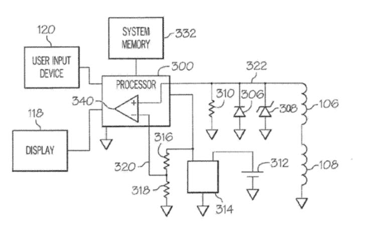
It's a comparator with a 1/2VCC input from voltage divider, and other input from two coils in series with zener and regular diodes and load resistor.

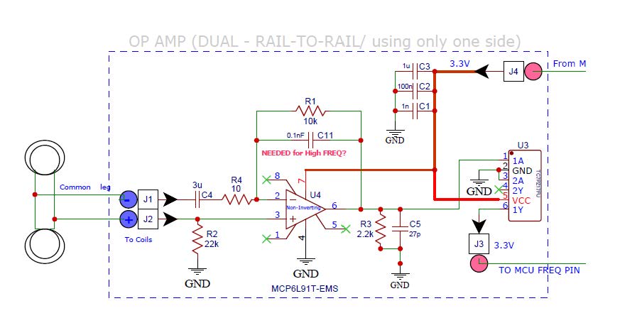
enter image description here

-20mV to +60mV

updated board with DC center added

\$\endgroup\$
13
  • 2
    \$\begingroup\$ Diodes should be added to protect inputs as in §4.1.2. Also, R4 seems a bit too low and I should lower R2 and add a capacitor and some "offset". \$\endgroup\$
    – Antonio51
    Commented Aug 1, 2022 at 5:57
  • 2
    \$\begingroup\$ @TommyS - Hi, You said in response to an earlier comment from Antonio51: "Not familiar with "§4.1.2. "". That means section 4.1.2 in the MCP6L91 datasheet which you linked in the question, entitled "Input voltage and current limits" on page 13 of the current version of the PDF file. In particular see figure 4-1 on that page, which shows the diodes referred to by Antonio51. I hope that helps. \$\endgroup\$
    – SamGibson
    Commented Aug 1, 2022 at 7:44
  • 2
    \$\begingroup\$ What's the amplitude of this so-called eddy current? \$\endgroup\$
    – Andy aka
    Commented Aug 1, 2022 at 7:53
  • 2
    \$\begingroup\$ Sounds like a reluctor sensor. Do you want to amplify the voltage or derive a digital output? Use a comparator if you want a digital output. Use two comparators if you want the positive and negative edges. I woukd suggest you don’t involve Eddy - he is innocent. I think it was Michael and his law of induction to blame for the observed effect! \$\endgroup\$
    – Kartman
    Commented Aug 1, 2022 at 22:16
  • 1
    \$\begingroup\$ From what @Kartman mentioned, I observed the electronic resemblance of Variable-Reluctance sensor is very high. The difference I would guess is that TommyS might be detecting a flux leakage with a sensor coil that does not provide a magnetic flux to the relative-moving counterpart, just detects it; probably resulting “Eddy’s” misnomer. I found an application note: maximintegrated.com/en/design/technical-documents/app-notes/1/… that shows how the small hysteresis available in a RS485 transceiver (as MAX485 too) could be used for that VR-sensor being converted to Digital. \$\endgroup\$
    – EJE
    Commented Aug 2, 2022 at 16:21

1 Answer 1

2
\$\begingroup\$

Don't know what happens with MCP6L91 op-amp (not in my database).
But here is the behavior with AD8591 (rail to rail, in my database) (AC analysis).

enter image description here

When the non-inverting is not polarized at 1.65V, the output is at -60db. When "well" polarized, it is a "band-pass" as usual.

NB: Must be checked in TRANsient Analysis with sinusoidal input, for example.

enter image description here

In red, what happens when V8=0, as in your "setup".

I also added the behavior with the "sensor" used. AC Analysis.
No fundamental change.

enter image description here

\$\endgroup\$
4
  • \$\begingroup\$ Thank you very much for the very well illustrated recommendation. I really appreciate the thoroughness. So based on what I understand from your post, fundamentally the current OP AMP circuit is suited for the expected frequency range, but I need to add a "DC point" at the + input (pin 3) of the OP AMP. Currently the DC level on + input of the OP AMP rests at zero which causes attenuation issues when voltage/current from the two sensors are applied. That DC point should be raised from zero to a constant 1.65V. Maybe I use a voltage divider from the VDD via 10K/10K resistors. \$\endgroup\$
    – TommyS
    Commented Aug 1, 2022 at 14:36
  • 1
    \$\begingroup\$ Right for your understanding. Voltage divider 10k/10k would be ok. Just don't forget a capacitor from the middle to the ground (>10uF would be ok). In fact, probably the input voltage is going below ground and becoming negative (not very "good" for some op-amp). \$\endgroup\$
    – Antonio51
    Commented Aug 1, 2022 at 14:45
  • \$\begingroup\$ Added the updated circuit diagram in my original post. Will modify the actual circuit, test it, and will report back. \$\endgroup\$
    – TommyS
    Commented Aug 1, 2022 at 18:05
  • 1
    \$\begingroup\$ Be aware that the gain could be too high. \$\endgroup\$
    – Antonio51
    Commented Aug 2, 2022 at 16:33

Your Answer

By clicking “Post Your Answer”, you agree to our terms of service and acknowledge you have read our privacy policy.

Not the answer you're looking for? Browse other questions tagged or ask your own question.