2
\$\begingroup\$

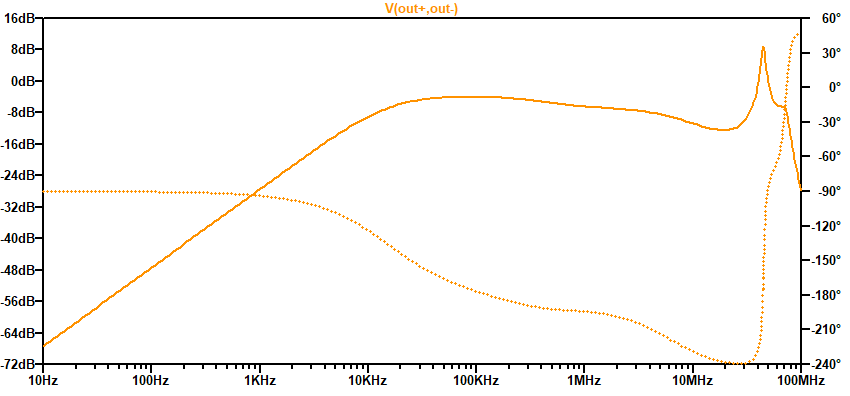
I want to amplify an output signal from a sensor. The sensor is made of three inductors which are coupled. One primary inductor with 25uH and two secondary inductors wired in the opposite direction with 3uH and 1uH. For the amplification I chose an instrumentation configuration which will be followed by a fully-differential op-amp. The amplifier is configured as a lowpass filter with two poles and a zero to even out the transfer function. The amplifier consists of two LT6230-10 op-amps. The transfer function looks like this and already gives a hint for a possible oscillation at about 40 MHz:

enter image description here

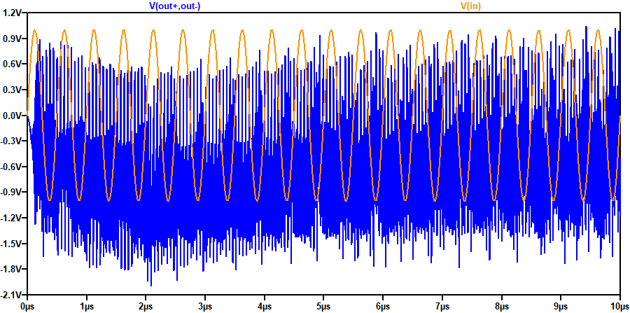
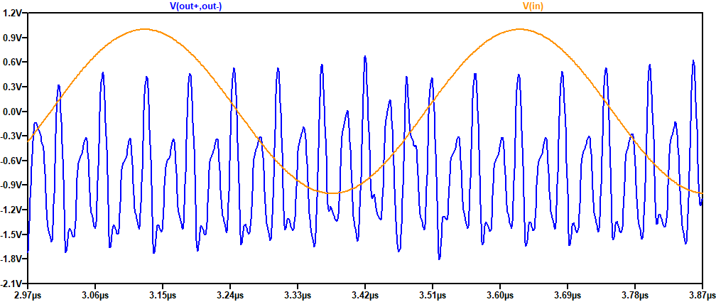
The output in time domain when exciting the sensor with a 2 MHz 1Vpp sine looks like this:

enter image description here

enter image description here

I thought this might be an issue caused by the feedback network with several capacitors. But when I simulated the circuit without the capacitors, there was still oscillation. Erasing the parasitics of the inductors doesn't change anything. I erased the center tap of the inductors, grounded inductor L8 and wired only one LT6230 as a buffer. It still oscillated. The oscillation stopped when I wired one LT6230 as a non-inverting amplifier with a gain of about 10.

I can't make the circuit work in the in-amp configuration though. No matter what gain I set without the feedback capacitors, it oscillates. This circuit or the op-amp seems to have trouble with the inductance at the op amp input. As an alternative I tried the OPA837, which had similar problems.

Can anyone tell me what is going on here and what could be done to stop the oscillations in the in-amp configuration?

\$\endgroup\$
6
  • 1
    \$\begingroup\$ Mildly related: what happens if you switch the polarity of L8? \$\endgroup\$ Commented Aug 2, 2022 at 15:29
  • 1
    \$\begingroup\$ Why is the value of L6, a different value L8? NB: if the input transformer is "wideband", a resistor between the outputs (top L6, bottom L8) can lower the peak. \$\endgroup\$
    – Antonio51
    Commented Aug 2, 2022 at 19:17
  • \$\begingroup\$ @aconcernedcitizen It oscillates too. \$\endgroup\$
    – TonyDublov
    Commented Aug 3, 2022 at 5:23
  • \$\begingroup\$ @Antonio51I can't go into detail about the sensor. I chose the in-amp because of its high input impedance. A resistor would lower the input impedance and doesn't help in the simulation. \$\endgroup\$
    – TonyDublov
    Commented Aug 3, 2022 at 5:28
  • \$\begingroup\$ @TonyDublov "Mildly related" was because, with a reversed polarity, the output signal will be a sum, instead of a difference, so you should get a larger signal to work with (given the small coupling and non-paired secondaries I presume you're dealing with physical limitations that should benefit from any improvement). Otherwise the selected answer does the job. \$\endgroup\$ Commented Aug 3, 2022 at 7:11

2 Answers 2

2
\$\begingroup\$

Be aware for wideband transformers.

The output parasitic capacities can create a "spike" in AC analysis.

Example: here for Cs = 2pF.

enter image description here

\$\endgroup\$
3
  • 1
    \$\begingroup\$ I am aware of that. I did the simulation without any parasitic capacitances of the indcutors. Maybe the problem is related to the inductance and the op-amps' input capacitances. \$\endgroup\$
    – TonyDublov
    Commented Aug 3, 2022 at 5:36
  • 1
    \$\begingroup\$ @TonyDublov If it is the opamp input C, then a series R with the transformer would help. \$\endgroup\$
    – tobalt
    Commented Aug 3, 2022 at 17:22
  • \$\begingroup\$ @tobalt Inserting a series resistor did the trick! The problem indeed was the op-amps' input capacitances together with the inductances. \$\endgroup\$
    – TonyDublov
    Commented Aug 3, 2022 at 19:35
7
\$\begingroup\$

You are using the LT6230-10 opamp which is only guaranteed stable for closed loop gains of 10.

At high frequencies the capacitative feedback you have will set a closed loop gain of much less than 10 because of C3/C4 and C1/C2.

Removal of C3/C4 and an increase in value of R13 should help. Or some other means to reduce the amount of feedback at high frequencies.

The LT6230 (without the -10 suffix) is stable down to unity gain but has a lower gain-bandwidth product.

In extreme cases a resistor capacitor network across the inputs of the opamp can help but at the expense of increasing the noise gain.

\$\endgroup\$
1
  • \$\begingroup\$ You are right about the LT6230-10. I simulated the circuit with the LT6230, the LT6230-10 and the OPA837. They are all oscillating even without any capacitors in the network. This configuration with the inductance at the input seems to be tricky to amplify with this in-amp configuration. I probably will go with a single-ended solution and filter in a second stage. \$\endgroup\$
    – TonyDublov
    Commented Aug 3, 2022 at 5:34

Your Answer

By clicking “Post Your Answer”, you agree to our terms of service and acknowledge you have read our privacy policy.

Not the answer you're looking for? Browse other questions tagged or ask your own question.