1
\$\begingroup\$

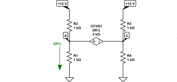
This is an exercise from Irwin's book, 9th edition.
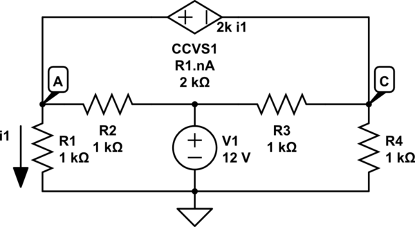
schematic

simulate this circuit – Schematic created using CircuitLab

Although the book calls for the use of nodal analysis, I decided to do it by mesh analysis (this is what I am currently training).

The question asks for the value of VC. After performing Mesh Analysis, I arrived at the matrix equation:

$$\begin{pmatrix} 2 &-3 &-1 \\ -1 &2 &0 \\ -1 &0 &2 \end{pmatrix}\begin{pmatrix} i_A\\ i_B\\ i_C \end{pmatrix}=\begin{pmatrix} 0\\ -12m\\ 12m \end{pmatrix}$$

Whose determinant is zero.

When I found a solution book on the internet, performing a nodal analysis, I arrived at the value of VC = 9 V. However, when performing the Super Node Equation, it considers VC - VA = 2·k·I1, which does not seem correct to me.

Anyway, am I wrong in assuming that there is no solution for this circuit? In case there is no such solution, what explanation could I have for this?

Thinking about the idea of building a circuit, it bothers me a bit that they don't have a solution. Is this due to the topological restrictions imposed by Kirchhoff's Law and Ohm's Law? Or is it a flaw in the theory trying to describe a real physical system?

Is my assembly in the simulator correct? In particular, how to realize the current-controlled voltage source?

\$\endgroup\$
6
  • \$\begingroup\$ Is that "R1.nA" really just I(R1)? And if so, which direction is considered positive? I don't understand the notation, I guess. Also, what's the point of nodes B and D? They are defined as 0 V. So I don't know why you placed them there. (And no, I don't have Irwin's book on hand.) \$\endgroup\$
    – jonk
    Aug 2, 2022 at 20:53
  • \$\begingroup\$ In fact, I agree that there is no need to indicate nodes B and D. As for the notation, I understand that R1.nA indicates the current going from node A towards resistor R1, in this case, the current that controls the voltage source is the one "going down" from node A towards GND. \$\endgroup\$ Aug 2, 2022 at 21:04
  • \$\begingroup\$ So is this image an accurate representation? \$\endgroup\$
    – jonk
    Aug 2, 2022 at 21:06
  • \$\begingroup\$ Exactly. I had just made the changes. I apologize for the confusion. \$\endgroup\$ Aug 2, 2022 at 21:10
  • \$\begingroup\$ Seems to solve out okay. Do you already have the answer from using a nodal approach? Okay. Well, never mind that! It solves out symbolically. But when the numbers are plugged in, then I think you may be right. I need to double check my work. \$\endgroup\$
    – jonk
    Aug 2, 2022 at 21:19

2 Answers 2

3
\$\begingroup\$

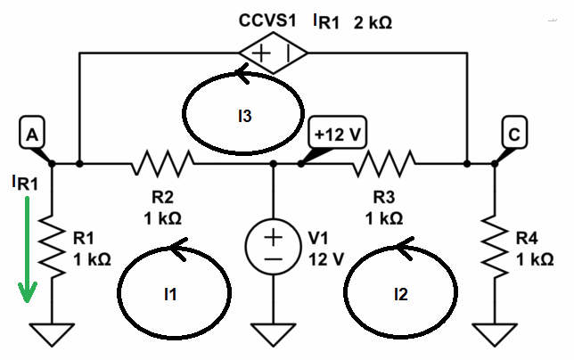
Adapting your diagram, here's how I'd plan out the mesh analysis:

enter image description here

$$\begin{align*} 0\:\text{V} + V_1 -\left(I_1-I_3\right)R_2 - I_1 \,R_1 &= 0\:\text{V} \\\\ 0\:\text{V} - I_2 \,R_4 -\left(I_2-I_3\right)R_3-V_1&= 0\:\text{V} \\\\ 0\:\text{V} -\left(I_3-I_1\right)R_2 -\left(I_3-I_2\right)R_3+I_1\,R_{_\text{CCVS}}&=0\:\text{V} \end{align*}$$

So the matrix I get is:

$$\left[\begin{smallmatrix} -R_1-R_2&0&R_2 \\\\ 0 & - R_3 -R_4 &R_3 \\\\ R_2+R_{_\text{CCVS}}&R_3&-R_2 -R_3 \end{smallmatrix}\right]\left[\begin{smallmatrix}I_1\\\\I_2\\\\I_3\end{smallmatrix}\right]=\left[\begin{smallmatrix}-V_1\vphantom{I_1}\\\\V_1\vphantom{I_1}\\\\0\vphantom{I_1}\end{smallmatrix}\right]$$

Or, dividing everything though by 1,000 and stuffing in values:

$$\left[\begin{smallmatrix} -2&0&1\vphantom{I_1} \\\\ 0 & -2 &1\vphantom{I_1} \\\\ 3&1&-2\vphantom{I_1} \end{smallmatrix}\right]\left[\begin{smallmatrix}I_1\\\\I_2\\\\I_3\end{smallmatrix}\right]=\left[\begin{smallmatrix}-12\:\text{m}\vphantom{I_1}\\\\12\:\text{m}\vphantom{I_1}\\\\0\vphantom{I_1}\end{smallmatrix}\right]$$

Signs different but the gist is the same.

For nodal analysis, I'd start here:

schematic

simulate this circuit – Schematic created using CircuitLab

But \$I_{R_1}=\frac{V_{_\text{A}}}{R_1}\$ so it follows that the voltage difference across the current controlled voltage source must be \$2\cdot V_{_\text{A}}\$. But this means that \$V_{_\text{C}}=-V_{_\text{A}}\$.

And, using Thevenin equivalents I find:

schematic

simulate this circuit

And there, the current must be the same throughout. But it cannot be the same throughout. So it cannot be resolved by nodal, either.

\$\endgroup\$
1
\$\begingroup\$

Following the suggestion to do it generically, I took R1 = R.

Then the Mesh Analysis equations are:

\$2i_A-3i_B-i_C=0\$

\$-i_A+(R+1)i_B=-12\$

\$-i_A+2i_C=12\$

With \$i_A\$, \$i_B\$ and \$i_C\$ being the loop currents.

From the second and third equation, I put \$i_B\$ and \$i_C\$ as a function of \$i_A\$, substituting in the first equation and solving, I get:

\$i_A = (25+R)/(R-1)\$

Therefore, the system has no solution the way it is described in the book.

I would be happy if someone could comment on the other questions asked in the initial question.

\$\endgroup\$

Your Answer

By clicking “Post Your Answer”, you agree to our terms of service and acknowledge that you have read and understand our privacy policy and code of conduct.

Not the answer you're looking for? Browse other questions tagged or ask your own question.