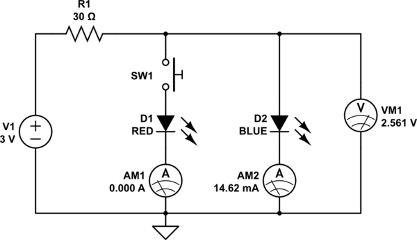
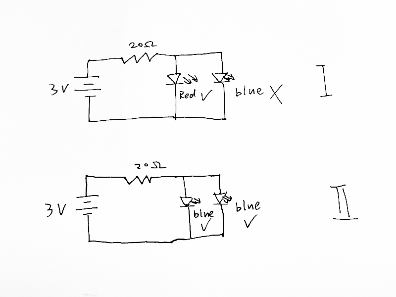
The red led acts as a shunt regulator. By putting various voltage shunts in parallel, the one with the lowest voltage "wins" and doesn't allow the voltage to increase. That's what a shunt regulator is, by definition: it limits the voltage by drawing current as the voltage goes up too high.
If you want to learn more about this concept, search using the term shunt regulator.
Now, LEDs may be crude shunt regulators, but consider that the circuit you've shown allows to use a SPST pushbutton as if it was an SPDT button. Shown below, when the button is depressed, the blue led turns off, and the red led turns on. The leds alternate, even though just a simple button is used.

simulate this circuit – Schematic created using CircuitLab
After opening the schematic in CircuitLab, click on SW1 to select it, and use Space to toggle the switch.


