0
\$\begingroup\$

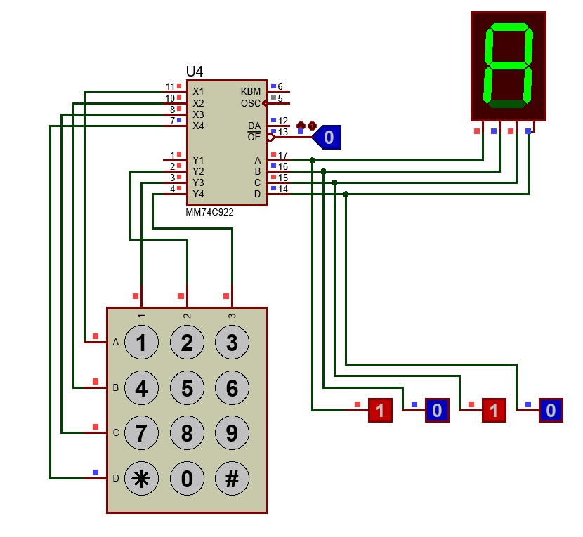
I've started doing some project that includes displaying entered digits via keypad phone in Proteus. I'll leave a screenshot below, so this post doesn't look undefined. You've probably seen this before.

I'd describe this as the first part of my project. I've seen it here in one of the posts, and also in some videos I've found on the Internet. Earlier I didn't know that there's an easier way to interface keypad, using component such as MM74C922. In my project I have to use keypad 4x3 and I'm not allowed to use any type of microcontrollers. Problem here is that when I start my simulation, zero is shown on the 7S display, when I press 1, 0 is shown, when 2 -> 1 is shown. Second row goes OK, but the 3rd acts pretty much the same 7 -> 8, 8 -> 9, pressing 9 displays nothing.

I understand that MM74C922 is most suitable for 4x4 matrix, results're definitely showing, but something confuses me, and by that I mean - how is it possible that some of the simulations I've seen work completely fine (using similar configuration), even with 4x3 keyboard? I'd appreciate any explanations and suggestions, if possible. Thank you in advance!

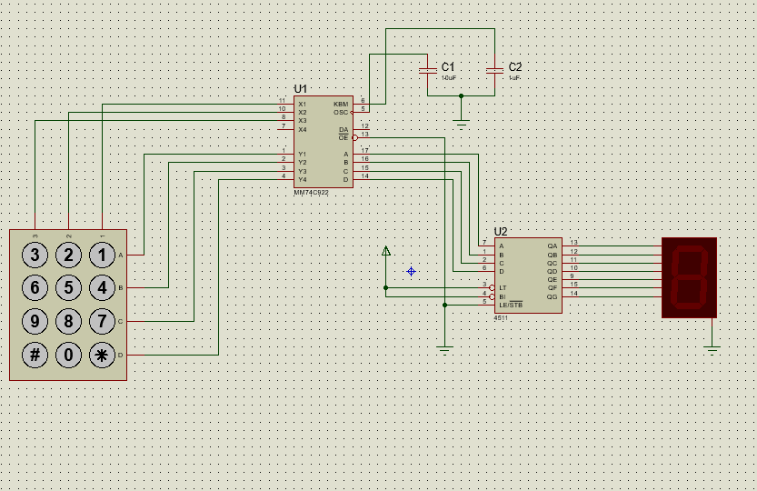
enter image description here

\$\endgroup\$

2 Answers 2

1
\$\begingroup\$

It's very simple, and the circuit works exactly as drawn. You only expect it to work differently.

The buttons in the button matrix short certain pins of the matrix decoder chip, and the decoder simply outputs a number (key code) for each button that happens to be pressed in the matrix.

The buttons in the keyboard just have labels printed on them that don't match the keycodes the matrix outputs, no matter how you wire it, due to the way the buttons are arranged in the matrix and connected to decoder chip.

As the decoder chip has four columns and four rows, each row must have 4 codes. But you have only 3 buttons per row, so you can't output all codes in a row, only three of them.

So the keycodes output will be in range of 0 to 15, and you will be skipping every fourth number. Therefore, by the time you reach your button which reads "9" on it, the output code is not within range of printable numbers 0..9 any more.

\$\endgroup\$
1
\$\begingroup\$

In that case you have to use a microcontroller (ARDUINO might work or you can use Attiny microcontrollers series since they have low number of pins and size) so that to Decode the BCD and to get the corresponding outputs. The Output of 4511 IC is only Decimals so when the MM74C922 sends the BCD for non Decimal output it fails to show the digit completely. Here is the starting solution to solve the issue.

  1. Analyze the 4-bit Encoder Values Encoder Output map for 3 by 4 keypad; Data table when button pressed:

    '1' = 0b0001; '2' = 0b0010; '3' = 0b0011; '4' = 0b1001; '5' = 0b1010; '6' = 0b1011; '7' = 0b0101; '8' = 0b0110; '9' = 0b0111; '0' = 0b1110; '*; = 0b1101; '#' = 0b1111;

Those Data are according to my circuit:

Circuit diagram to analyze data table for 3 by 4 keypad with MM74C922.1

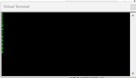
When I used Arduino the code where something like this (code generated by ChatGPT), The problem with these codes is that they print out the reading BCD every time the void loop() starts over. If one could modify them so that to print one digit at a time and the Arduino to print the next pressed digit only when pressed. The problem with MM74C922 is thet, it doesn't have reset pin or perhaps I don't know how to get it out of holding state;

const int pinMMA = 6;
const int pinMMB = 7;
const int pinMMC = 8;
const int pinMMD = 9;

void setup() {
  Serial.begin(9600);

  pinMode(pinMMA, INPUT);
  pinMode(pinMMB, INPUT);
  pinMode(pinMMC, INPUT);
  pinMode(pinMMD, INPUT);
}

void loop() {
  // Read BCD values from pins
  int bcdValue = digitalRead(pinMMA) << 3 | digitalRead(pinMMB) << 2 | digitalRead(pinMMC) << 1 | digitalRead(pinMMD);

  // Display the corresponding string in the serial monitor using if statements
  if (bcdValue == 0b0001) {
    Serial.println("1");
  } else if (bcdValue == 0b0010) {
    Serial.println("2");
  } else if (bcdValue == 0b0011) {
    Serial.println("3");
  } else if (bcdValue == 0b1001) {
    Serial.println("4");
  } else if (bcdValue == 0b1010) {
    Serial.println("5");
  } else if (bcdValue == 0b1011) {
    Serial.println("6");
  } else if (bcdValue == 0b0101) {
    Serial.println("7");
  } else if (bcdValue == 0b0110) {
    Serial.println("8");
  } else if (bcdValue == 0b0111) {
    Serial.println("9");
  } else if (bcdValue == 0b1110) {
    Serial.println("0");
  } else if (bcdValue == 0b1101) {
    Serial.println("*");
  } else if (bcdValue == 0b1111) {
    Serial.println("#");
  }
  delay(500);  // Adjust delay as needed
}

It works but need more mods.

Arduino uno proteus virtual terminal.

\$\endgroup\$

Your Answer

By clicking “Post Your Answer”, you agree to our terms of service and acknowledge you have read our privacy policy.

Not the answer you're looking for? Browse other questions tagged or ask your own question.