What I really want to know is that how much PWM voltage magnitude (Vgate-using MOSFET, Vbase-using BJT) should be when I use MOSFET or BJT as switch. Of course it must depend on the input voltage.
It will not depend on the input voltage in a well designed SMPS but rather operate at a fixed voltage for MOSFET. For a BJT, the story is very similar, the base current will not depend on the input voltage but in an advanced design, it could be dependent on peak current. Let's ignore this for now and call it constant base current.
For a MOSFET, you need your Vgs to be at least Vgsth, the threshold voltage for the MOSFET you've chosen, but in practice more than that. 10 V is common for low voltage MOSFETs and 15 V for high voltage dito. You want to fully switch the MOSFET on and never stay in the linear region.
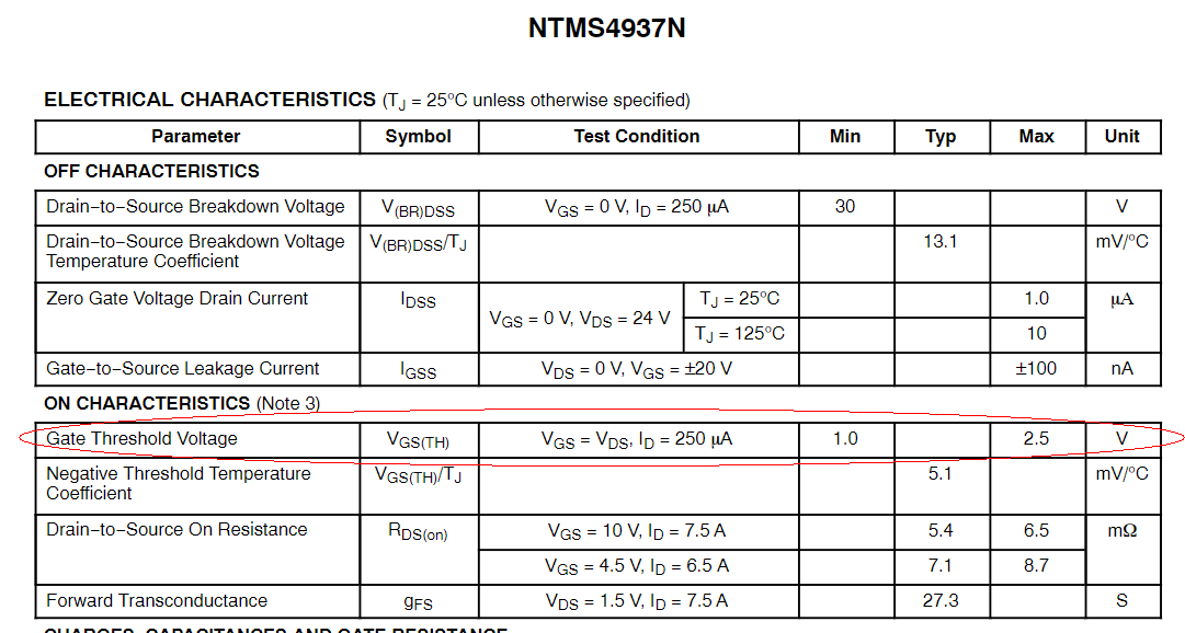
Here is a datasheet for a MOSFET picked at random:

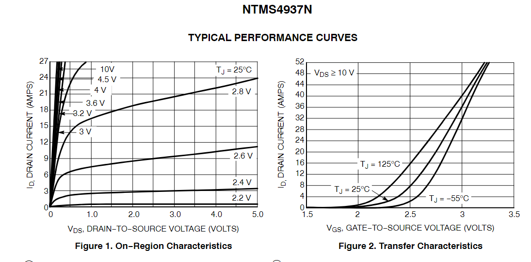
Below 2.5 V Vgs will be a disaster. More specifically, you want to look at the transfer characteristic:

You want Vds to be as small as possible, so you choose a Vgs to be high enough to satisfy this. At 3 V, the curve starts to straighten out. If your current isn't too high, this plus margin would do the job. The higher your current, the higher you need to go in Vgs to not have excessive losses.
As long as you stay below absolute max Vgs with margin, there is little penalty in going unnecessary high Vgs, so you will often find gate voltages twice what the transfer characteristic calls for in commercial power supplies.
For a BJT, you will be about 0.7 V above the emitter voltage, with a base current strong enough to stay away from the linear region, effectively Ipk < Ibase*hfe(min).
No one designs buck converters with BJTs these days, so you probably want to focus your efforts on MOSFETs and the gate drive of them.


