1
\$\begingroup\$

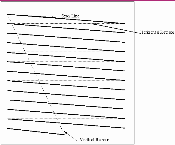
CRT display

When I see above image, I'm able to make sense of terms like vertical/horizontal blanking. When I come across diagrams like this: snapshot of this:

Teledyne LeCroy

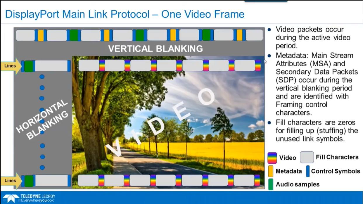
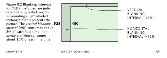
Similarly, a snap of this: Charles Poynton

I'm not able to understand what x and y axes represent and if the whole rectangle represents a digital display, then does it mean that picture is displayed only on a portion of the total available area?

\$\endgroup\$

2 Answers 2

1
\$\begingroup\$

The diagram shows the blanking intervals as if they were pixels of a larger image with no blanking. This is a very useful way to visualize blanking intervals. How else would you do it?

As a creator of a video signal, your job is to create a signal with the correct timing. Maybe you could count the timing as a certain number of microseconds of hsync, a certain number of microseconds of front porch, a certain number of pixels with a certain number of microseconds per pixel, then a certain number of microseconds of back porch, but it's easier to measure the entire thing in pixels, and likewise it's easier to measure the entire vertical thing in lines (aka pixels).

The last diagram says that there are 480 lines on the screen plus a blanking interval equivalent to 45 lines. The same for horizontal, but the numbers aren't shown.

Note that actual blanking is for CRT displays and irrelevant for LCD screens. LCD screens often still use it for historical compatibility. The DisplayPort diagram shows the blanking times are used to transfer metadata and audio.
\$\endgroup\$
1
\$\begingroup\$

Displays need horizontal and vertical synchronization, and for many reasons, such as compatibility with analog transmission timing or transmitting audio along the video, the active digital image you transmit might be 720 pixels per line and 480 lines, but the digital line with blanking area has 858 pixels total and digital frame in total has 525 lines with blanking area.

These areas not used for active picture were used in analog video for synchronization signals and allowing time for the CRT beam to fly back to beginning of horizontal or vertical start position. In digital world (ITU-R BT.656) these analog portions are replaced by digital start and end of video code sequences so the pixels previously used for analog blanking and synchronization can be repurposed for metadata packets that contain info about signal or other data such as audio.

\$\endgroup\$
0

Your Answer

By clicking “Post Your Answer”, you agree to our terms of service and acknowledge you have read our privacy policy.

Not the answer you're looking for? Browse other questions tagged or ask your own question.