0
\$\begingroup\$

I'm making a secondary battery pack for a tiny drill, and I wanted this 18650 spare battery pack, always being charged (stored) so it can be always ready to use. However, the Li-ion batteries don't like it to be kept fully charged for a long time as it severely affects their capacity. It seems that a voltage of 3.7v~4v would be a good storage voltage for that purpose.

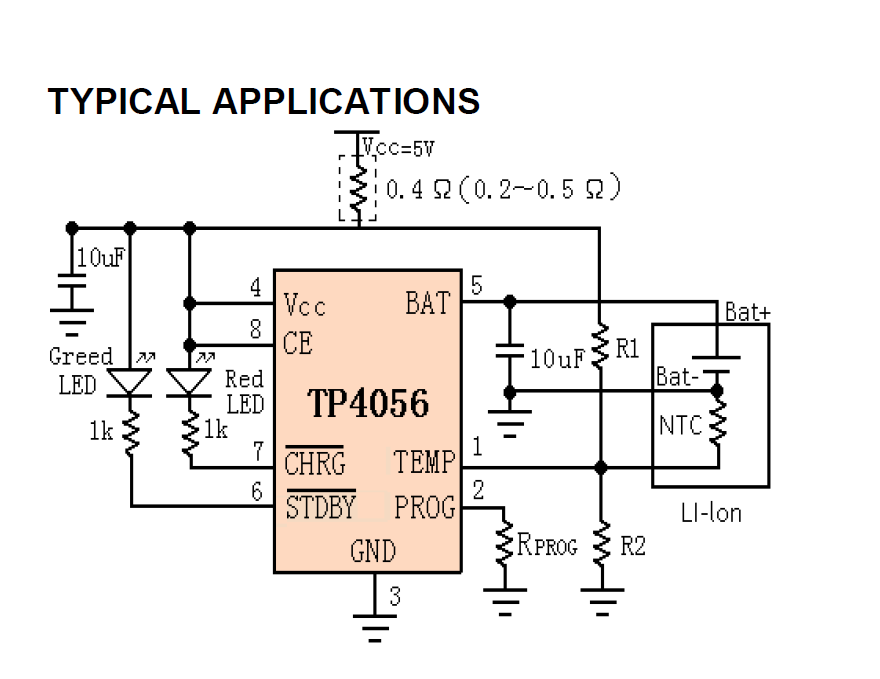
I'm using this simple TP4056 charging ICs, and their full-charge termination voltage is 4.2V.

TP4056 typical application

Is there any trick to make the termination voltage lower than 4.2v?

I thought of using a diode in series with the battery, but I think it would be troublesome as the chip wouldn't be able to read the voltage back to check if it's charged or not.

\$\endgroup\$
4
  • \$\begingroup\$ You could add a series power diode to battery to reduce CV mode voltage at 10%CC rate cutoff by choice of power diodes, but what will reset the charger after battery slow self decay. Choice of diode will affect results. A smarter charger will handle this automatically. \$\endgroup\$
    – D.A.S.
    Commented Aug 29, 2022 at 17:43
  • \$\begingroup\$ Two 0.2V Schottky diodes in anti-parallel, in series with the bat +? Never tried this, would be an experiment. \$\endgroup\$
    – rdtsc
    Commented Aug 29, 2022 at 17:50
  • \$\begingroup\$ @rdtsc Well I'm going to test that. gonna report soon :) \$\endgroup\$ Commented Aug 29, 2022 at 18:17
  • \$\begingroup\$ @rdtsc The solution worked as you expected it although the chip never reached the termination (which is obvious). However the battery is kept at a nominal of 4v and the idle current is quite safe and acceptable. You may now post it as an answer. \$\endgroup\$ Commented Oct 29, 2022 at 17:17

2 Answers 2

1
\$\begingroup\$

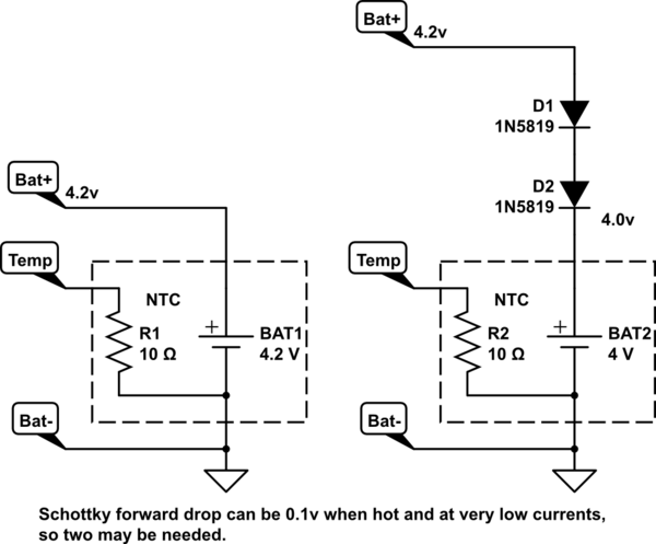
Since you tried it and it worked (congratulations), I'll expand on my comment further.

schematic

simulate this circuit – Schematic created using CircuitLab

The forward voltage drop of the 1N5819 will drop significantly as it gets hot. Suggest using a hot-air tool on these diodes in operation, set to 100°C or hotter you ever expect the circuit could reach, and observe what affect this has on the final battery voltage. With two diodes, there is likely enough margin for this to be acceptable. With one diode, the result might be too high.

Other Schottky diodes have slightly different low-current "knees", so it might be possible to use a combination of different diodes to get a slightly higher or lower value. This is best measured experimentally, as most datasheets do not give forward voltages for very low currents (microamps.)

\$\endgroup\$
1
  • \$\begingroup\$ Well it was anti-parallel as you mentioned in the original comment. like two diodes paralleled back to back, not in series. \$\endgroup\$ Commented Oct 30, 2022 at 8:29
2
\$\begingroup\$

This chip doesn't offer a lot in the way of controls or customisation, there isn't a way to simply configure the chip to stop at a lower voltage. The best option I can offer you is to introduce a supervisory system that pulls CE low when the target storage voltage is reached.

A different chip may be more suited for this task, and this is a good task. My experience has shown that cell balance improves and gas generation is kept down when properly stored; we dramatically increased our batteries lifetime when we started doing this.

\$\endgroup\$

Your Answer

By clicking “Post Your Answer”, you agree to our terms of service and acknowledge you have read our privacy policy.

Not the answer you're looking for? Browse other questions tagged or ask your own question.