Correct me please. As far as I know the magnetic flux density B is a function of current, core permeability and its geometry. So let's take a power transformer rated to S VA. So it can withstand \$I_{RMS} = \frac{S}{V}\$ (where V corresponds to its primary or secondary voltage) amperes of RMS current. So the peak current used to find B is \$I = I_{RMS}\cdot\sqrt2\$. So the core won't saturate at the same DC current in one single winding as it doesn't care about DC and AC, just a current creating a field. So what am I missing? And what actually VA rating can say about DC capability of the transformer?
-
1\$\begingroup\$ DC current would be assumed to be zero for all practical AC equipment examples. \$\endgroup\$– winnyCommented Sep 1, 2022 at 19:50
-
\$\begingroup\$ Are you talking about power transformers? In that case, the core flux density depends on the voltage, instead of the current. Typically, a DC bias in the voltage can lead the core to semi-cycle saturation. You can search at Google for "core saturation semi cycle" to have an idea. \$\endgroup\$– Luiz OliveiraCommented Sep 1, 2022 at 19:57
-
\$\begingroup\$ @LuizOliveira Yes. To be more specific about the possible use of them as chokes. So I should've formulate the question clearer. How to find (let's say I know the number of turns and core permeability) a flux density in the core under a load? I suppose what I'm missing is the fact that I have to subtract primary and secondary fields. \$\endgroup\$– e_asphyxCommented Sep 1, 2022 at 20:02
-
1\$\begingroup\$ Transformers make very bad, heavy, expensive chokes, because chokes have to store energy (transformers don't store energy). Air is much better at storing energy than iron or ferrite, which is why chokes, inductors and flybacks use gapped cores. If you want to replace the air-gap with iron or ferrite, you need a huge length of it to get the same energy storage. Using air is lighter, smaller and cheaper. \$\endgroup\$– Neil_UKCommented Sep 2, 2022 at 10:51
2 Answers
So the peak current used to find \$B\$ is \$I=I_{RMS}\cdot \sqrt2\$.
No, that is not the case.
The load current passing into the transformer primary and exiting on the secondary has nothing to do with core saturation. The only current that causes core saturation is that flowing into the transformer primary when the secondary is unloaded. It's called the magnetization current.
Of course, magnetization current is still flowing when load currents are also present but, it is the magnetization current alone that dictates core saturation.
In more depth
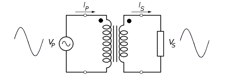
Secondary load current is 180° out of phase with the primary referred load current because while primary referred load current flows into the transformer, secondary load current flows out (respecting the dots): -
Hence, both primary and secondary load magneto motive forces cancel or, put another way, the primary referred load ampere-turns are cancelled by the secondary ampere-turns.
And what actually VA rating can say about DC capability of the transformer?
It says nothing apart from the main reason that a regular transformer cannot be used to transmit DC to the secondary (except for short periods in time and that isn't really DC is it).
Transformer image modified/simplified from here
-
\$\begingroup\$ Cool, thank you. Now everything started to make sense \$\endgroup\$– e_asphyxCommented Sep 1, 2022 at 20:24
Calculate it backwards instead. Say we have a transformer with Ae = 200 mm2, le = 240 mm, μr = 10k, and Bsat = 1.2 T.
First, solve for turns:
$$ N = \frac{ V_\textrm{rms} }{ 4.44 B_\textrm{sat} F A_e } $$
At 60 Hz, 120 V needs 1876 turns.
This will have an inductance of \$L = \frac{\mu_r \mu_0 A_e N^2}{l_e}\$ = 19.6 H.
H is a conversion factor between flux and current. We know the flux (\$\frac{V\textrm{rms}}{4.44 F}\$), so divide by inductance to get magnetizing current:
Imag = 23 mA
Importantly, this figure doesn't depend upon frequency; the developed voltage will simply be proportional to frequency (well, not completely, in practice -- because reasons -- but, to the level being modeled here, it's good enough). This includes down to DC, though we need to remember this is the RMS current, whereas saturation occurs near the peaks: multiply by \$\sqrt{2}\$ or 32.5 mA peak, and we finally arrive at the DC figure.
Note that any DC bias, reduces headroom for actual AC to be transformed, so a real transformer connected to mains might only handle a few mA DC before drawing excessive current peaks.
@Andyaka has explained how this can be so much less than load current (which, for a transformer this size, will be an ampere or so).

