0
\$\begingroup\$

I want to output 12V 45 watts to turn on a 12V 45 watt LED (motorcycle headlight). The image given is schematic of my target project. I need to draw only 15 watts from the battery and the rest of the energy will come from the "Rectified AC Source". If I just connected them in parallel the battery could be charging itself even draw all power from the battery. But by some magical way I need to draw only 15 watts from battery and rest from the AC source.

The AC source is just motorcycle's headlight socket's power. Which produces 30 watts at most. (Since the existing bulb is 30 watt halogen.)

Scheme

\$\endgroup\$
8
  • 3
    \$\begingroup\$ Some helpful search terms for you: "Load sharing" and "load balancing". \$\endgroup\$
    – Hearth
    Commented Sep 10, 2022 at 17:52
  • 1
    \$\begingroup\$ LED bulb ratings don't always say what power they actually consume, and just because a socket used to have a 30W device in it doesn't mean that it can't supply 45 watts just fine, and AC is different from DC. So please edit your question so that we know if the LED bulb is rated for AC, if it actually consumes 45W or if it is a "45W equivalent" to a 45W halogen, the current rating of your bike's alternator, and the current rating of the fuse, if any, in the headlamp circuit. \$\endgroup\$
    – TimWescott
    Commented Sep 10, 2022 at 18:23
  • 1
    \$\begingroup\$ If you have a 30W halogen bulb in there now and you replace it with a decently-efficient LED bulb that actually consumes 45 watts, then you may find that you're now producing way too much light. \$\endgroup\$
    – TimWescott
    Commented Sep 10, 2022 at 18:24
  • 2
    \$\begingroup\$ Does the bike's alternator not already charge the 12V battery? \$\endgroup\$ Commented Sep 10, 2022 at 19:01
  • 1
    \$\begingroup\$ Motorcycle power systems vary. Some power the headlight through a separate AC winding on the alternator, and the headlight goes out when the engine stops. Since you mention AC on the headlight socket I am guessing this is what you have, right? Exactly which LED bulb do you have, and what is the motorcycle brand/model? \$\endgroup\$ Commented Sep 10, 2022 at 20:51

1 Answer 1

0
\$\begingroup\$

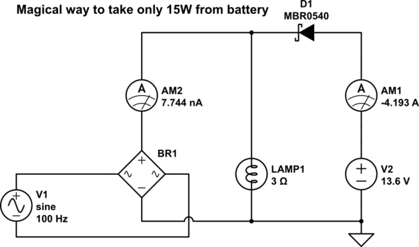
Since the alternator is an AC source, we get pulsed current behind the rectifier. The battery can fill the gaps between the pulses. My first attempt would be a simple parallel ciruit with an additional diode to avoid a charge current flowing from the alternator back to the battery.
This may work perfectly and is worth an experiment. V1 is the alternator, the simulation is not very realistic, because its inductance is ignored here. If I add an inductor in series with V1, the simulator dies.
schematic

simulate this circuit – Schematic created using CircuitLab

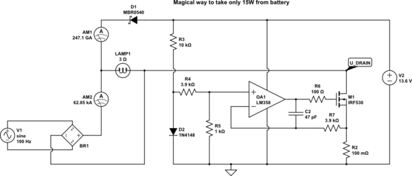
If the above is not sufficient, a true current limiter for the battery side is possible. This is not very efficient, the MOSFET M1 must dissipate 12 W worst case. The circuit limits the battery current to 1.2A during the gaps. During the peak current pulses from the alternator, the battery current drops to zero. So the average load on the battery is a bit lower than 15W. A lower value for R4 can allow more battery current, this can be adjusted in a real world circuit.
schematic

simulate this circuit

D2 is used as a cheap voltage reference and the voltage divider R4/R5 sets the target current for the battery.

A more efficient solution would involve a current limited SMPS stage, I will draw one, when I have some more time.

\$\endgroup\$

Your Answer

By clicking “Post Your Answer”, you agree to our terms of service and acknowledge you have read our privacy policy.

Not the answer you're looking for? Browse other questions tagged or ask your own question.