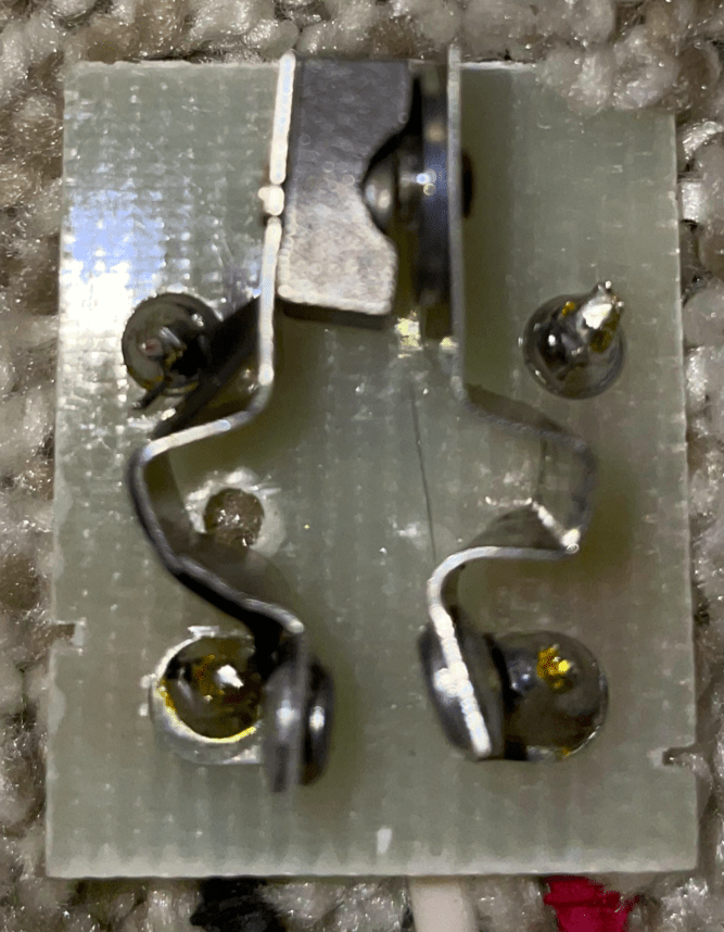
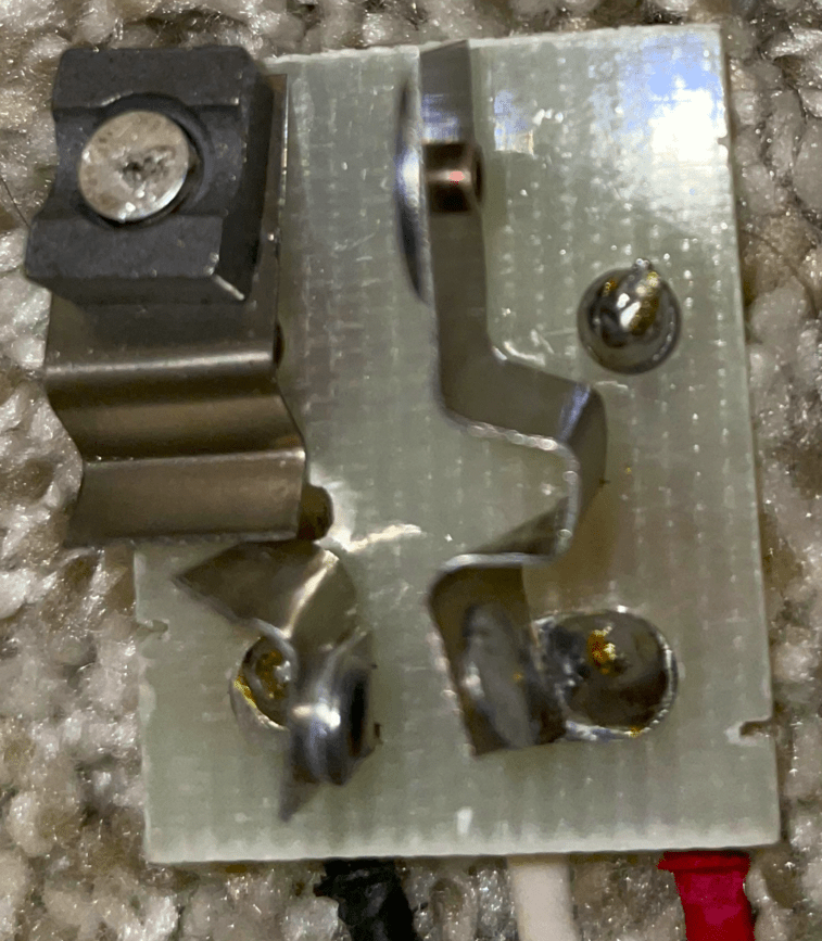
This is a thermal time-delay relay, a surprisingly complicated little device. This one is Ugly, true, but it looks like it's been run over a couple of times.
Pre-LED street lights used HID (High Intensity Discharge) lamps (bulbs). HID lamps have a warm-up stage that doesn't work properly if the bulb is already hot. To keep from short-cycling the bulb if the power is glitched long enough for the arc to extinguish the thermal delay keeps the lamp ballast de-energized long enough for the lamp to safely restart.
The bimetals are mounted to move the contacts to the left when heated and to the right when they are cooled. They have the bendy contour to provide more length for the bending effect. Without the magnet present, they would move left and right in unison, never touching, as the ambient temperature changed. The contact travel distance is only a few millimeters.
The bimetals carry the load current for the lamp and its ballast, but this current doesn't produce any heating that affects their operation in the relay. The bimetal on the left carries an old fashioned ceramic magnet that is unaffected by heat in the environment or by heat generated in the operation of the relay or by the lamp circuit.
The bimetal on the left has a resistive heater attached to its left side, but it's not clearly visible in the photos. The heater is in the form of a long, flat insulated packet of fine nichrome wire bonded to the bimetal with an adhesive. When energized, the nichrome outputs a couple of watts (max) of heat into the bimetal, causing the bimetal to bend left if it's unrestrained. Bimetals bend a definite amount at a given temperature. If they are restrained, they exert a pushing or pulling force. The left-hand bimetal responds to the temperature of the environment plus the heat from the heater. The right hand bimetal responds only to the temperature of the environment inside the chassis. This way the effect of environmental temperature on the force on, or the distance between the electrical contacts cancels out, leaving only the effect of the heater. The resistor current therefore controls the gap between the electrical contacts on the moving ends of the bimetals. The magnet performs two roles. Firstly, it helps provide hysteresis, (a "dead band" bracketed by an on-threshold and off-threshold) where the heater current must reach a high level to open the switch contacts and a lesser current to close the switch contacts. There are two switching thresholds, not just one. When the heater current gets high enough, and the magnet moves close enough to the steel washer on the right-hand bimetal, the magnet suddenly pulls the two contacts together with a "snap" that is very easy to see and hear. Against the force of the bimetals' springiness (bimetal strips are very springy) the magnet holds the contacts closed. It takes noticeable force to separate the magnet from the washer when the heater current is adequately reduced or cut off, so when the force of the left bimetal pulling the magnet finally becomes high enough (due to continued cooling toward ambient temperature) the magnet finally pops loose of the washer with a visible and audible "sproing" motion. The dead band between the contacts opening and closing is the key to the timing function. It takes time for all this heating and cooling to take place and that timing is fairly predictable because of the compensating function of the right-hand bimetal.
The second role of the magnet is to minimize contact damage due to the arcing and erosion that occur when mechanical switch contacts are slowly brought together or separated.
The photocells that I've seen in these types of sensors are about 2.5cm in diameter brown discs with a squiggle pattern on their face. These are usually cadmium sulfide (CdS) photoresistors. One outstanding feature of CdS cells is that they are very slow to respond, sometimes taking the better part of a minute to settle down on an ohmmeter. Photocells for operating relays are very large because they switch the relay coil current with no electronics at all and they need the surface area to handle the current and line voltage.
Notice in all this that the heater must be energized to open the switch contacts. When the heater turns off, the street light turns on. This particular thermal time-delay relay is always warm to the touch in the daytime when the lamp is off. You can see the delay function in a thunderstorm when a bright lighting flash shuts off the streetlights. The photoresistor (photocell) is slow to respond to changes in light, and it will integrate a bright flash. A bright flash will feed the heater enough current to separate the magnet from the washer.
In the photos, I believe the white wire is one of the heater leads and the other heater lead is connected to the black wire. There's a remnant of a small black wire on the top left terminal in the first photo. I believe that connects to the white wire. Inside the street light, the white wire would connect to one side of the the photocell, and the other side of the photocell would connect to 120/240VAC power, and the red wire is the lamp load.
[1] As the word "bimetal" as it's used in electricity. "Bimetal" refers to a thin, bonded, two-layer sheet or strip of two metals that expand at different rates when heated or cooled. This makes the strip bend a little bit as it's heated or cooled. Bimetals are widely used as mechanical actuators in thermostats. The two blades in our relay are bimetal strips. Standard terminology calls each of these a bimetal.


