1
\$\begingroup\$

I'm working on a transformer active battery balancing circuit and have it working except, due to the diode voltage drop on the secondary, I need an alternative.

Since the battery cell voltage is 4 V, a 1 V drop is 25% efficiency loss and obviously will have huge imbalance issues. I thought about adding another winding on the transformer to increase the voltage but would instead like to add a active diode.

I tried the following circuit design but it's not working. The IGBT is not turning on fully and only allowing 1.5 V through. I am using a RJP30E2 which has a saturation voltage of 1.7 V. The transformer is running at 120 kHz.

I have very little experience and understanding of electronics and started this project a few weeks ago.
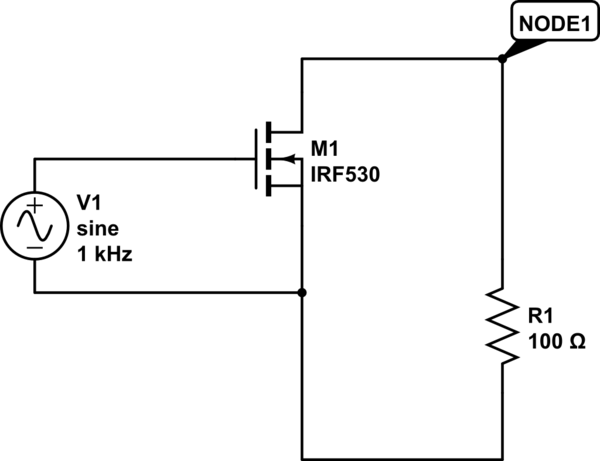
schematic

simulate this circuit – Schematic created using CircuitLab

\$\endgroup\$
14
  • 1
    \$\begingroup\$ Why can't you use MOSFETs a la H-bridge? \$\endgroup\$
    – Andy aka
    Commented Sep 15, 2022 at 18:23
  • 1
    \$\begingroup\$ Please show the circuit that doesn't work. The link shows a circuit with a transformer and diodes \$\endgroup\$ Commented Sep 15, 2022 at 18:33
  • \$\begingroup\$ All the mosfets I looked into have a too high of a gate voltage \$\endgroup\$ Commented Sep 15, 2022 at 18:48
  • \$\begingroup\$ heres the correct link: falstad.com/circuit/… \$\endgroup\$ Commented Sep 15, 2022 at 18:50
  • 1
    \$\begingroup\$ ive redid the schematic with circuit labs and embeded it into the question \$\endgroup\$ Commented Sep 15, 2022 at 19:14

1 Answer 1

2
\$\begingroup\$

Although 15 A is a lot of current for a logic-level MOSFET, all hope is not lost.

Take, for instance, a DMN2011. Let's look at the datasheet.

First things first, lets check out the Electrical Characteristics on Page 2 and see what the "On Characteristics" looks like. We want to scrutinize the "Static Drain-to-Source On-Resistance":

enter image description here

This is looking promising! Let's investigate further.

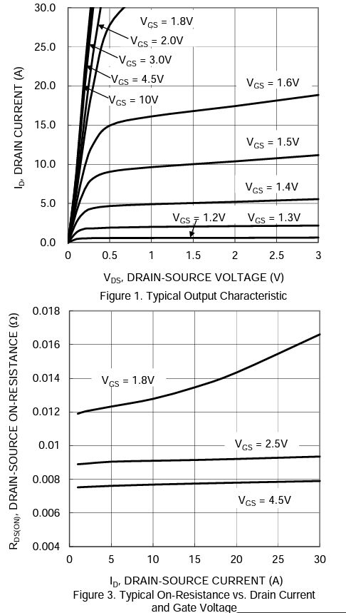
On page 3, figures 1 and 3:

enter image description here

Figure 1 shows us that current is pretty linear with voltage at 15 A with Vgs of 1.8 V and higher.

Figure 3 shows us that the drain to source resistance at Vgs of 2.5 V and 15 A is only about 0.009 Ω. Nine Milliohm!

Using Ohm's law, 15 A over 9 mΩ drops only 0.135 V.

Depending on your other requirements, something like this could work.

\$\endgroup\$
2
  • 1
    \$\begingroup\$ Thank you so much! I have no clue how you found this but so far this seems perfect. First time ordering on digikey, hopefully it arrives soon and this fixes the problem. Was worried that I was missing something other than the Vgs being not low enough. \$\endgroup\$ Commented Sep 15, 2022 at 20:57
  • 1
    \$\begingroup\$ @robertkaras I don't know what the rest of your circuit looks like, so there is still room to mess it up! :-) If it doesn't work, come on back and we'll get it sorted out. \$\endgroup\$ Commented Sep 15, 2022 at 21:00

Your Answer

By clicking “Post Your Answer”, you agree to our terms of service and acknowledge you have read our privacy policy.

Not the answer you're looking for? Browse other questions tagged or ask your own question.