0
\$\begingroup\$

I've been struggling with getting this circuit to work. My objective to try to use low-power (3.3 V/μA), low-cost, jellybean components. The idea of this circuit is that we have six latching buttons for tamper detection connected to one single dedicated pin while in a battery operated backup mode.

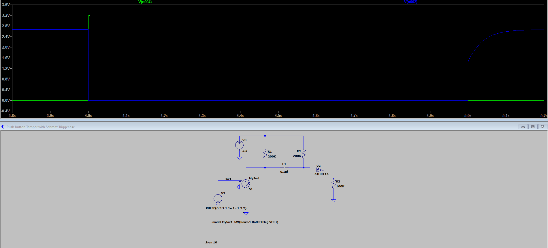
In a tamper situation the button toggles the inputs state from open-circuit to ground which generates a single sharp drop of capacitor charge which goes into a hex Schmitt trigger inverter which outputs this glitch as a positive pulse. The reason for using this RC circuit is that I need to be able to manipulate my 1 interrupt pin (dedicated) to get an interrupt from all six switches without having a single switch to latch the pin to ground indefinitely, making it impossible to detect any further tamper switching events.

enter image description here

Blue trace = switch (pressed = 0 V) Green trace = inverter output

After building this circuit it works when the pull-up and the resistor in the RC circuit at the input of the inverter do not exceed 22 kΩ The Problem is that the the Schmitt trigger inverter input struggles to work with weaker pullups (680 kΩ for example). My intention is to have the lowest possible current consumption.

The inverter I'm using an M74HC14 as this what is available in my local area. I've scoured the internet for quite some time but I've not found any datasheet stating anything of help. Are there any types of inverter/Schmitt trigger that work without problems with big resistors at their inputs?

I've thought of maybe using inverting buffers which have Schmitt trigger inputs, but they are going to be ordered internationally so I would really appreciate it if someone could shed some light on what to look for if they tolerate the high resistor pull-up situation.

Another take I may just ditch the Schmitt trigger inverter and just rely on pure RC circuitry. Now this circuit works if implemented with one switch and the output works like shown below without problems.
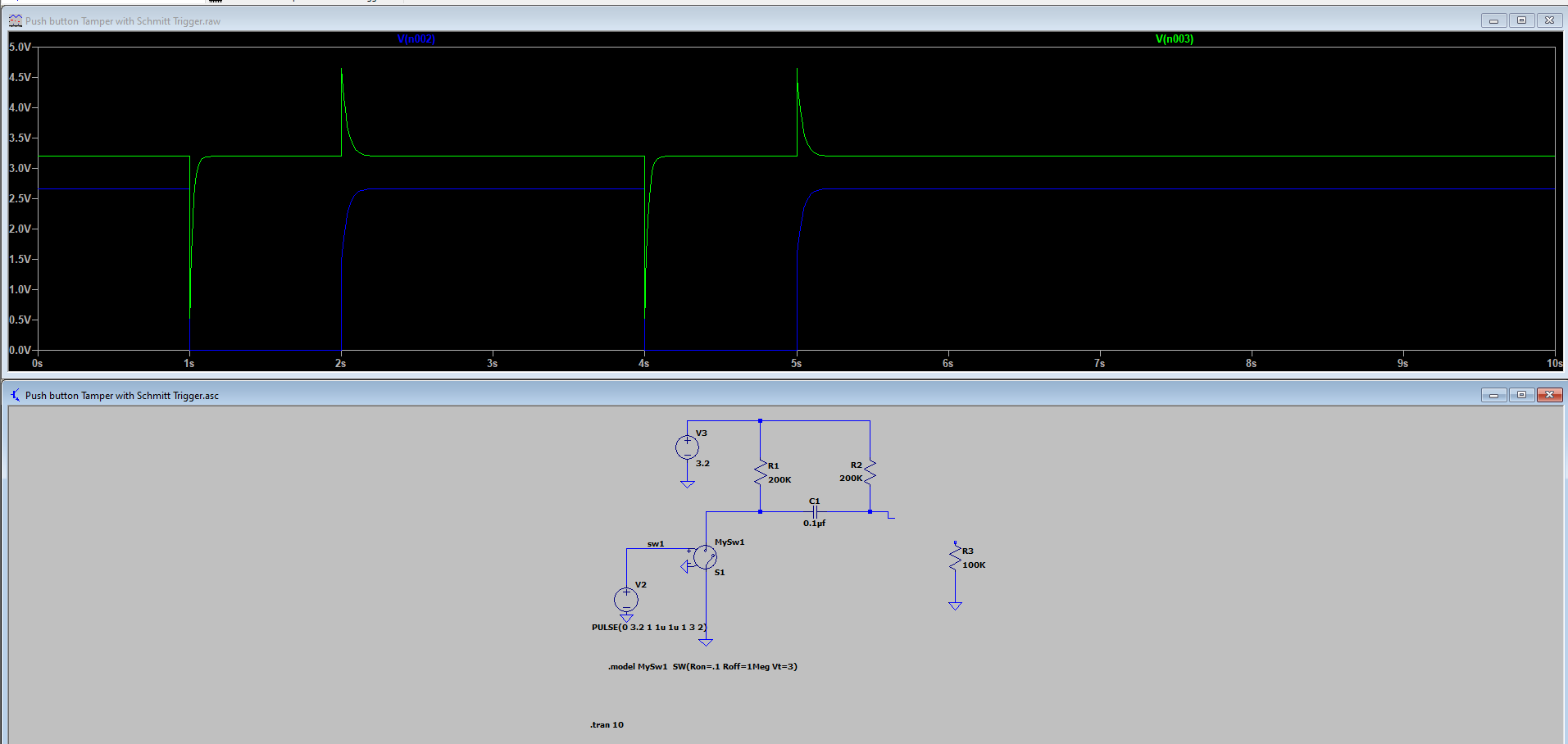
enter image description here Blue trace = Switch (pressed = 0V) Green trace = RC Circuit output (@ R2 & C1)

The problem starts when I try to duplicate this circuit and make a total of 6 parallel circuits. I tried separating each out of a circuit with a series diode and of course I installed a clamp diode right where I tie the outputs together to one pin, but the circuit would get worse and anyway would not work when compared to just 1 circuit alone**, the voltage drop at the output of RC Circuit now does not drop to zero, drops down from 3.2 V maybe to around 2.44 V (low) which is far the region to be recognized by the microcontroller as a zero (low).

If anyone needs more information, please let me know, and thanks to everyone for taking the time to read this thread.

\$\endgroup\$
8
  • \$\begingroup\$ ”as this what is available in my local area” Mouser, Digi-Key, RS and Farnell ships all over the world. Buy the components you need is my general advice. \$\endgroup\$
    – winny
    Commented Sep 16, 2022 at 15:37
  • \$\begingroup\$ And that is what I'm willing to do , but I would need to verify before buying that there are Schmitt trigger inverters/buffers that would actually do anything different than the one I have. Reason is that shipping and customs are expensive where I live and shipments take some time to arrive. \$\endgroup\$ Commented Sep 16, 2022 at 15:42
  • \$\begingroup\$ I see. Except for startup behavior, you should be able to get very realistic results with a 74HC model in LTspice. But for starters, you need to “supply” the Vcc to it via a spice directive. Right click on your Schmitt trigger and enter Vhigh=3.2. \$\endgroup\$
    – winny
    Commented Sep 16, 2022 at 15:54
  • \$\begingroup\$ @jonk yes ,yes, yes, yes & yes . Adding to that taking into consideration is cost, flexibility(jellybean) and low power since the device is battery operated. The device I'm working on is intended to have several lines of tamper switches so that the first accessible location when tripped it will stay tripped, the mcu should be able to detect any other tamper switch on the same output line , switches will be un-triggered as soon as the device gets assembled back together again. \$\endgroup\$ Commented Sep 16, 2022 at 22:02
  • \$\begingroup\$ Here is the story ; I'm working on a device that is battery operated thus current consumption important. The device is required to monitoring any types of tampering attempts like from opening some parts which are carefully placed inside of the enclosure which are going to get tripped once opened, jus to clarify the switches used (DPDT) are configured so that the switches are normally pressed (open circuit) as long as there is no tamper, as soon as the switches are released/tamper tripped they connect the common pin to ground. \$\endgroup\$ Commented Sep 17, 2022 at 10:27

2 Answers 2

2
\$\begingroup\$

I would have thought that the energy consumed was independent of the size of R2. The important thing is that you keep R1 high in value to limit the current being sunk through the switch when it's closed.

When the switch closes both sides of the capacitor will instantly drop to 0V, then the right hand side of the cap rises to Vcc. It takes the same amount of charge and energy to charge the capacitor no matter what the size of R2. The power dissipated in R2 will be larger for a smaller resistor but the capacitor will charge more quickly keeping the energy consumed the same. Increasing the size of the capacitor would result in higher energy usage. So I would say, you can reduce the size of R2 and if you can tolerate a short output pulse because you don't increase the size of the capacitor then the energy usage will be unchanged.

Q = CV

E = 0.5*CV^2

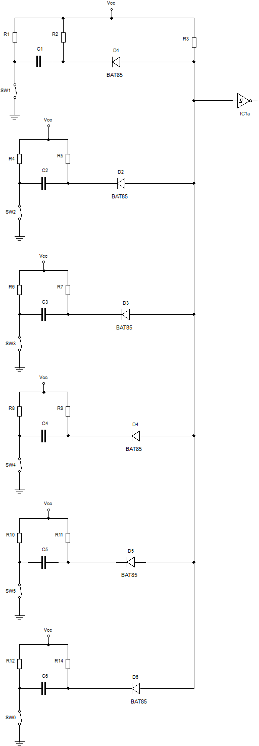
Circuit Diagram

The diodes and R3 form an AND gate and isolate the 6 sections from each other. The diodes also stop the positive going spike that occurs, when a switch is released, from reaching the Schmitt trigger IC. The BAT85 diodes are schottky diodes selected for there low forward voltage drop.

If you were to do without the Schmitt trigger then in order to get a positive going pulse you would need to invert everything - Swap over the positions of the switch and R1, connect R2 & R3 to ground instead of Vcc and rotate the diode by 180 degrees.

Schmitt trigger or no Schmitt trigger, switch bounce causing multiple interrupts may be a problem. You would need to debounce the switches. To debounce in software you could have a software delay of, say, 20ms as soon as you enter the interrupt service routine after which the switch bouncing would be over and it would be safe to exit the ISR. This is not good technique because, generally speaking, the ISR should be kept as short as possible. Alternatively, as soon as the ISR is entered you could disable the interrupt and start a hardware timer counting. After, say 20ms, the timer times out and causes an interrupt at which point you would re-enable the interrupt.

\$\endgroup\$
1
\$\begingroup\$

Another information that is useful to drive your design: when choosing weak pullup/pulldown resistors you have to take into account the input leakage current of the input you are driving.

This current (\$I_I\$ in your datasheet) will flow in the pullup/pulldown and generate a voltage drop that could mess with your logic thresholds.

In this case \$I_I=1\mu A\$ (worst case), so for a 680kohm pullup this means about 680mV. For a system powered at 3.3V this could be enough to reduce the noise margin of the input substantially.

In particular note the input threshold values (\$V_{t+}\$ and \$V_{t-}\$). The datasheet doesn't report values for Vcc=3.3V, however the values of \$V_{t+}\$ (for example) for Vcc=2V and 4.5V (worst case) are just 1.0V and 2.3V respectively. For 3.3V it will be somewhere in-between, so we could well take \$V_{t+}\approx 1.6V\$.

This means that the leakage current in the 680k pullup will make your input trigger just when the input signal is 1600mV-680mV=920mV. This may be a dangerously low threshold, since any kind of noise with about 900mV amplitude (for example some runt pulse caused by switch bouncing) will make your input change state.

Of course this is just a ballpark analysis, but you should get the point.

\$\endgroup\$

Your Answer

By clicking “Post Your Answer”, you agree to our terms of service and acknowledge you have read our privacy policy.

Not the answer you're looking for? Browse other questions tagged or ask your own question.