I'm building a 64:1 multiplexer, using 9 ADG408s (64:8:1). Last night, I had one of the chips on a bread board and was taking some measurements.
Everything worked as expected, except I observed a very large crosstalk signal (many orders of magnitude higher than the datasheet suggests). When I add a 1 kΩ pull-down resistor to the output, the crosstalk goes away; details below.
My setup looks basically like this:
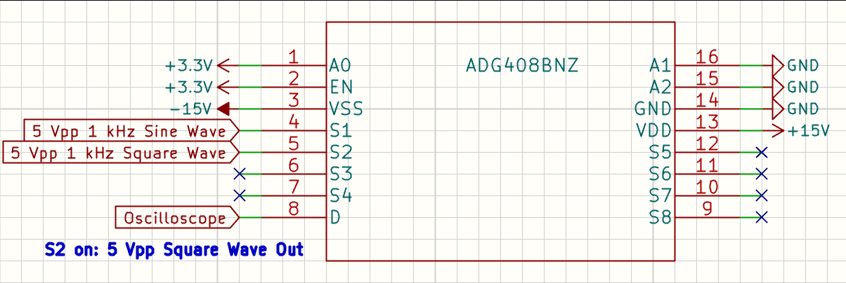
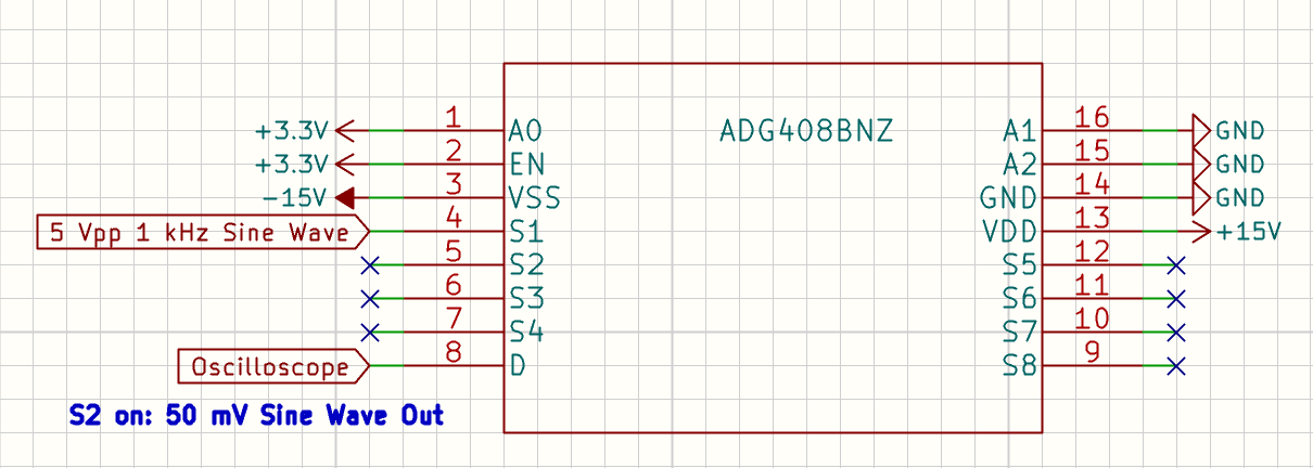
Pins A0-A2 set the channel. (0, 0, 0) sets channel S1 and (1, 0, 0) sets channel 2. The top figure shows channel 1 selected, and the second figure shows channel 2 selected.
I started by applying a 5 Vpp, 1 kHz sine wave to channel 1 and a 5 Vpp, 1 kHz square wave to channel 2. I switched pin A0 between GND and 3.3 V and observed the change in signal on my oscilloscope. Everything looked as I would expect.
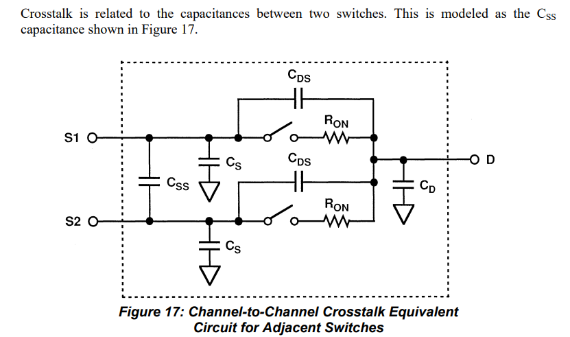
However, if I select Channel two (1, 0, 0) and disconnect the 5 Vpp square-wave signal from pin 5 (channel 2), I observe a 50 mVpp sine wave (crosstalk from channel 1). This is much larger than the -85 dB quoted value in the datasheet. See figure below:
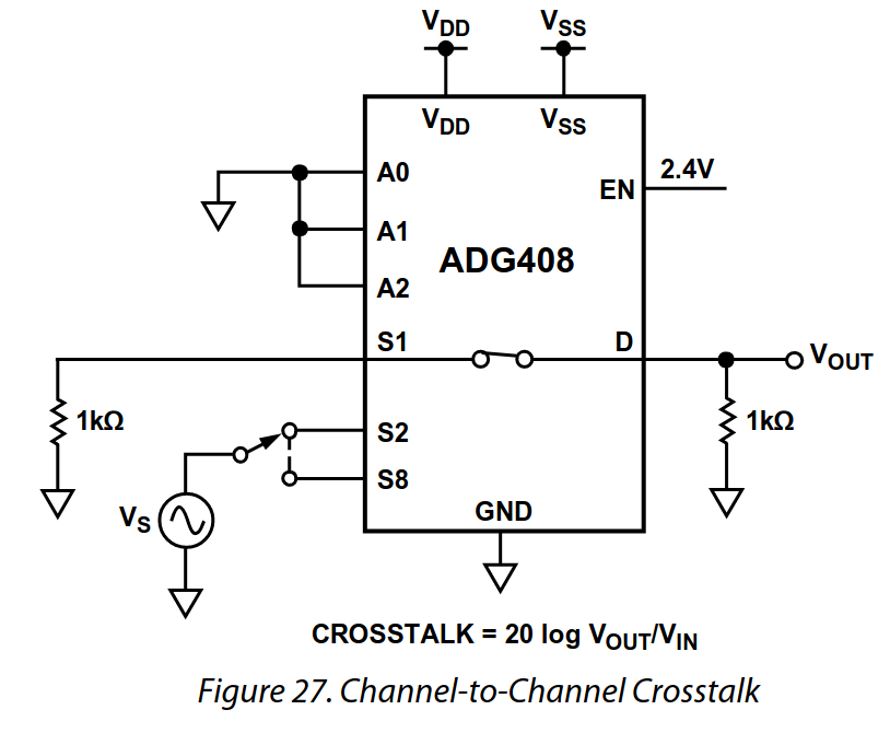
In the datasheet, figure 27, the crosstalk measurement shows a pull-down resistor between the output and ground. It also shows a similar resistor across the input. See figure below, which shows how the crosstalk was measured:
Note that channels 1 and 2 are switched in my setup (I'm applying the signal to channel 1 and measuring the crosstalk on channel 2. Sorry for any confusion).
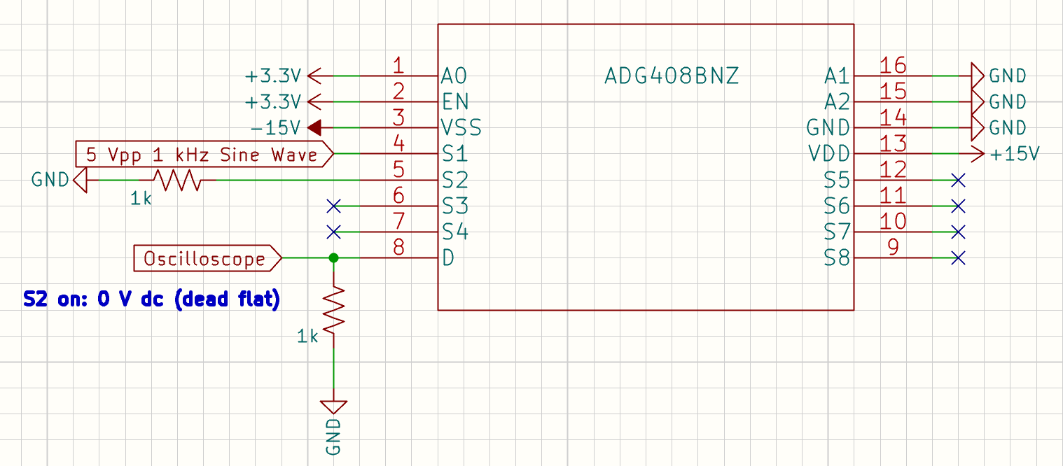
When I add 1 kΩ resistors to channel 2, connecting it to ground, and across the output to ground, the crosstalk goes away completely (at least I can't see it on my oscilloscope). See figure below:
If I remove the resistor on the input, the signal stays flat (i.e., no crosstalk). So it seems the resistor at the output is doing most of the work. I did some research and it seems that this might be charge injection and the resistor is allowing the charge to bleed off.
But I still have some confusion as to what exactly is going on and how to generalize these results. Since my final design will use 9 ADG408s (64 signals going into 8 ADG408s going into a single ADG408), I'm wondering how many resistors I need to add to my PCB design. Should I add these to the inputs just to be safe (that would be a lot of resistors)? Also, these resistors will affect the singal amplitude as they will form voltage dividers with the internal resistance of the ADG408 (which is about 70 Ω, but is not constant). If anyone can shed some light on this, I would greatly appreciate it. The AD website has a few tidbits here and there. It seems that crosstalk and multiplexers comes up a lot, but I couldn't find anything comprehensive. I also checked Horowitz, but there was no mention of crosstalk withing the context of multiplexers.


