2
\$\begingroup\$

I have designed a PCB based on the STM32L443VCT6 microcontroller.

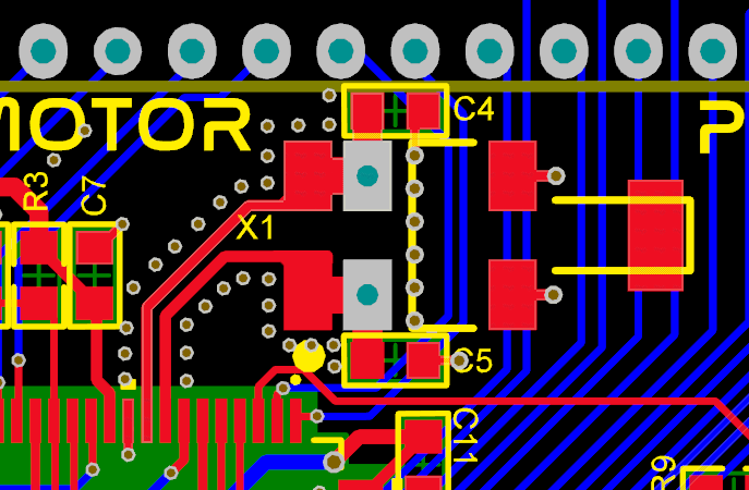
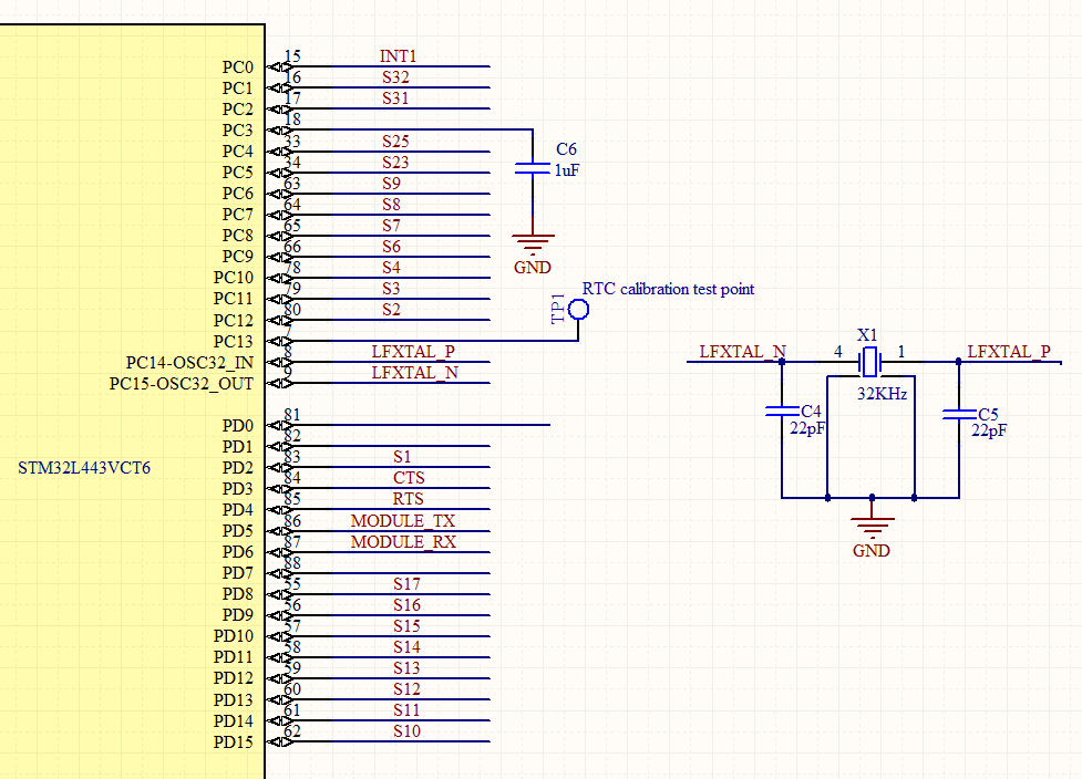
I used an external 32.768 kHz crystal (CM200C32768HZFT) crystal with two 22pF capacitors. I can successfully program the code but the MCU won't run.

When debugging the program, it gives RTC error, and the code does not run. This does not happen to all circuits, sometimes it works with another PCB.

Why is it happening? Does anybody know the cause?

Layout of Crystal Schematic of Crystal

\$\endgroup\$
8
  • 3
    \$\begingroup\$ You're going to need to add a lot more information, like some relevant bits of code and schematic to get a good answer. \$\endgroup\$
    – Colin
    Commented Sep 26, 2022 at 9:28
  • 1
    \$\begingroup\$ Even though scope probes introduce capacitance in the circuit, you can measure the clock with a scope. Basically, is there a sine wave on the crystal pin? If so, great, the hardware is working. If not, then the problem could be either in hardware or software. \$\endgroup\$
    – Lundin
    Commented Sep 26, 2022 at 9:33
  • \$\begingroup\$ Also unrelated to your question, I very much doubt that the stuff around R3 and C7 is more sensitive than the oscillator. Move the oscillator closer to the MCU and move the R3 + C7 stuff out of the way if needed. Via curtains are nice but it's more important to reduce the length of the traces. \$\endgroup\$
    – Lundin
    Commented Sep 26, 2022 at 9:36
  • 1
    \$\begingroup\$ Check AN2867: Oscillator design guide, especially chapter 7 "Tips for improving oscillator stability". \$\endgroup\$
    – Velvet
    Commented Sep 26, 2022 at 10:08
  • 1
    \$\begingroup\$ Crystal data sheet says, "Do not connect to terminals 2,3" with no explanation. Have you tried lifting the crystal from those two pads (on your PCB, they are grounded)? \$\endgroup\$
    – glen_geek
    Commented Sep 26, 2022 at 12:53

3 Answers 3

2
\$\begingroup\$

From the datasheet, it shows that your crystal part number CM200C32768HZFT suggesting that the crystal's load capacitance is 12.5pF, assuming your PCB tray capacitance is 5pF, then the C4, C5 capacitor value should be (12.5-5)x2 = 15pF, so your capacitor values of 22pF is too high, uses 15-18pF will probably works.

\$\endgroup\$
2
\$\begingroup\$

I had very similar issue in the past, but with another chip. You may need Rext, see AN2867 pages 11 and 16 for background and calculations. Try putting 10k resistor as Rext.

\$\endgroup\$
1
\$\begingroup\$

I assume you did not hand-assemble these units yourself and the handling and cleaning was done by others.

Tuning fork crystals are sensitive to shock and to things like ultrasonic cleaning, which can permanently damage them. Some similarly-packaged devices warn of possible exposure of the crystal metal housing below the molding, which could cause a short (probably less likely in this case).

Suggest you investigate further by swapping crystals on the failed units with known-good parts, with a careful inspection of the soldering after the original part has been removed.

\$\endgroup\$

Your Answer

By clicking “Post Your Answer”, you agree to our terms of service and acknowledge you have read our privacy policy.

Not the answer you're looking for? Browse other questions tagged or ask your own question.