3
\$\begingroup\$

I've been thinking about monitoring the power draw within my solar-based chicken coop setup to get a better understanding of the true power consumption for estimating battery life.

I have a 12 V deep cycle RV battery taking in solar power (through an appropriate charge controller) and supplying power to some USB cameras and a 12 V RV fan, controlled by a thermostat circuit.

I want to use an Arduino with an INA219 Adafruit breakout to monitor and log the current draw of the various components I have hooked up.

My understanding is that I would split the +12 V wire and use those to feed the breakout's Vin+/Vin- terminal block.

I have a couple of questions to make sure I don't fry the board:

  1. The Adafruit page has a big disclaimer:

Be careful inserting noisy loads that can cause a sharp current draw, such as DC motors, since they can cause problems on the power lines and may cause the INA219 to reset, etc. When using a DC motor or a similar device, be sure to include a large capacitor to decouple the motor from the power supply and use a snubber diode to protect against inductive spikes.

What do I need to do to protect the circuit, I assume mostly from the fan? I'm not sure how to decouple the other parts of the circuit with a capacitor and snubber diode, so any advice here is highly appreciated. This is the part I'm most worried about since I understand inductive loads can supply a pretty strong back-EMF if not accounted for.

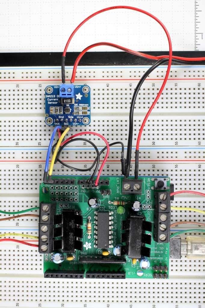
  1. The Adafruit wiring guide shows connecting the breakout ground, the Arduino ground, and the "high-side" ground all together. Is this normal, and are there any concerns about connecting the 12 V- (ground) and the Arduino ground (powered by a car 12 V to USB hub) together? I guess in theory it's all the same ground reference, but I'm unsure here. Maybe in the picture below they are powering the breakout using the shield's power, so this may be misleading, but I'm still uncertain.

enter image description here

  1. I also believe I need to swap out the sense resistor for a lower ohm rating. Is there a specific Digi-Key part number to use to get more than 3 A of measurement? Do I need to do something special in the code to adjust the breakout to be able to measure ~5 A?
\$\endgroup\$
3
  • \$\begingroup\$ Additionally, would it make more sense to use Adafruit INA260 instead? \$\endgroup\$
    – Drise
    Commented Oct 3, 2022 at 16:32
  • \$\begingroup\$ Hi Drise. I suggest you look the datasheet of MAX9919 mouser.com/datasheet/2/256/MAX9920-1514342.pdf. Last year I made a dual ammeter with this IC using arduino nano and works perfect also with 5A. This IC also supports measure of current on solenoids, electrical motors without worry. \$\endgroup\$
    – marcosbc
    Commented Oct 4, 2022 at 3:49
  • 1
    \$\begingroup\$ @marcosbc Thanks for that information. Unfortunately wiring up individual IC's is a bit above my skill level. I'm a software engineer by trade that knows just enough about electronics to make use of I2C breakouts and the Adafruit libraries provided with them. I can typically stumble through something a little more complex, like an analog output, but I have no experience or confidence in wiring up a circuit with bare ICs without a lot of assistance. \$\endgroup\$
    – Drise
    Commented Oct 4, 2022 at 15:00

1 Answer 1

3
+50
\$\begingroup\$

I'll keep it brief -- feel free to add comments if you need more clarity.

  1. A snubber diode is nothing more than a diode in parallel with your load in reverse polarity. It essentially gives the back-EMF a place to go when the load is switched off. Also called a flyback diode at times - https://en.wikipedia.org/wiki/Flyback_diode. I'll address the decoupling capacitor next.

  2. You actually NEED the grounds connected together for the INA219 to work reliably. It needs a reference to the main voltage. If grounds aren't connected, it's not guaranteed that the current sensing inputs will be within their absolute maximums. So connect the ground of the Arduino to the ground of your main power. The fact that you're using a 12V to USB hub to power it actually helps with the decoupling you're asking about in your first question. My best guess is that the "resetting" it's talking about would likely be due to the large motor load pulling down the voltage supplied to the small INA219, causing a brown-out condition. The USB hub should automatically provide some level of decoupling. Try without any extra capacitors. If operation is spotty, add a 10 uF electrolytic cap across your +5V/gnd power lines for the Arduino, and then add a 0.1 uF ceramic cap across your power pins for each of your boards as close to the device as possible. The idea is for the capacitors to provide little "boosts" of energy as needed whenever the main line voltage sags down, and by doing so, keep the microcontrollers from experiencing low voltage conditions.

  3. I can't be sure (haven't found a BOM for the board), but it looks like it's just a precision 2512 surface mount resistor.

"A precision amplifier measures the voltage across the 0.1 ohm, 1% sense resistor. Since the amplifier maximum input difference is ±320mV this means it can measure up to ±3.2 Amps."

So if you want more current range, use a smaller resistor. For example, a 0.05 ohm resistor would give you up to ±6.4 Amps of measurement range. Resistor TLRP3A30WR050FTE could be one option. I chose it based on resistance, being the correct size, having a low tolerance, and high power rating just in case there are current surges so it doesn't burn up.

\$\endgroup\$
2
  • \$\begingroup\$ Will any diode work for a flyback, or does it need to have specific characteristics? I also know there are many names for various types of diodes, is there a specific type I should use? As far as the capacitor is concerned, I already have another Arduino running off the USB hub and it doesn't seem to care when a load is turned on, so you're probably right it is not needed. \$\endgroup\$
    – Drise
    Commented Oct 6, 2022 at 16:55
  • \$\begingroup\$ Most any diode works as long as it can stand off the supply voltage (dc reverse voltage greater than the supply voltage) and has at least a little bit of current carrying capacity -- what that "little bit" is depends on the application. Even something as basic as a 1N4001 will work. My go to for the boards I make is the SM4007PL-TP. The 1000V reverse breakdown is WAY overkill, but they're cheap, and there's never an application I have in my line of work where they won't function as intended for me. \$\endgroup\$ Commented Oct 11, 2022 at 23:17

Your Answer

By clicking “Post Your Answer”, you agree to our terms of service and acknowledge you have read our privacy policy.

Not the answer you're looking for? Browse other questions tagged or ask your own question.