Can someone explain how this circuit is working? How is the victim node voltage increasing through the leakage current?
Here is the image for more context:
(Source: Team VLSI - Crosstalk Noise and Crosstalk Delay – Effects of Crosstalk)
Can someone explain how this circuit is working? How is the victim node voltage increasing through the leakage current?
Here is the image for more context:
(Source: Team VLSI - Crosstalk Noise and Crosstalk Delay – Effects of Crosstalk)
It might be easier for you to picture it if you instead interpret the impedances in the system as resistances.
The impedance of a capacitor is very low at high frequencies. Think about what the transient on the aggressor line looks like in the frequency domain - the faster the transient, the higher frequency components it must have.
The impedance of the driver for each line (aggressor and victim) is not zero. The traces on the PCB have some parasitic resistance, inductance, and reactance.
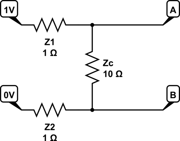
If you mentally picture these impedances as resistors, in a kind of instantaneous snapshot of the circuit's operation, you can get a feel for why a voltage is induced in the victim line:

simulate this circuit – Schematic created using CircuitLab
The actual numbers here are arbitrarily chosen. All that matters is the overall behaviour.
The aggressor line has an impedance of 1Ω from its driver. The same applies to the victim line. The capacitor has an instantaneous impedance of 10Ω during the transient.
This forms a divider circuit. We can calculate the induced voltage in the victim line (i.e. the voltage at B) as:
$$V_{B} = \frac {Z_2} {Z_1 + Z_C + Z_2} \times V_1 = \frac {1\Omega} {1\Omega + 10\Omega + 1\Omega} \times 1V = 83mV$$
Assuming equal impedance for both drivers during the transient, we can also show that the aggressor line suffers a voltage dip equal to the induced voltage in the victim line:
$$V_{A} = \frac {Z_1 + Z_C} {Z_1 + Z_C + Z_2} \times V_1 = \frac {1\Omega + 10\Omega} {1\Omega + 10\Omega + 1\Omega} \times 1V = 0.917V$$
Now think about the situation at low frequencies or DC. Capacitors have high impedance at low frequency, so \$Z_C\$ will be very high. Let's arbitrarily pick 100kΩ as an example:
$$V_{B} = \frac {Z_2} {Z_1 + Z_C + Z_2} \times V_1 = \frac {1\Omega} {1\Omega + 100000\Omega + 1\Omega} \times 1V \approx 10\mu V$$
There is still a very small amount of induced voltage in the victim line, but it is far less due to the high impedance of the capacitor.