I'm trying to reverse engineer a communication line between two components. However for debugging I'm connecting to only one of them, powering it up and looking at the signal. I have no experience with this so I'm really stumbling around with some basic knowledge and having once or twice used an oscilloscope 15y ago.
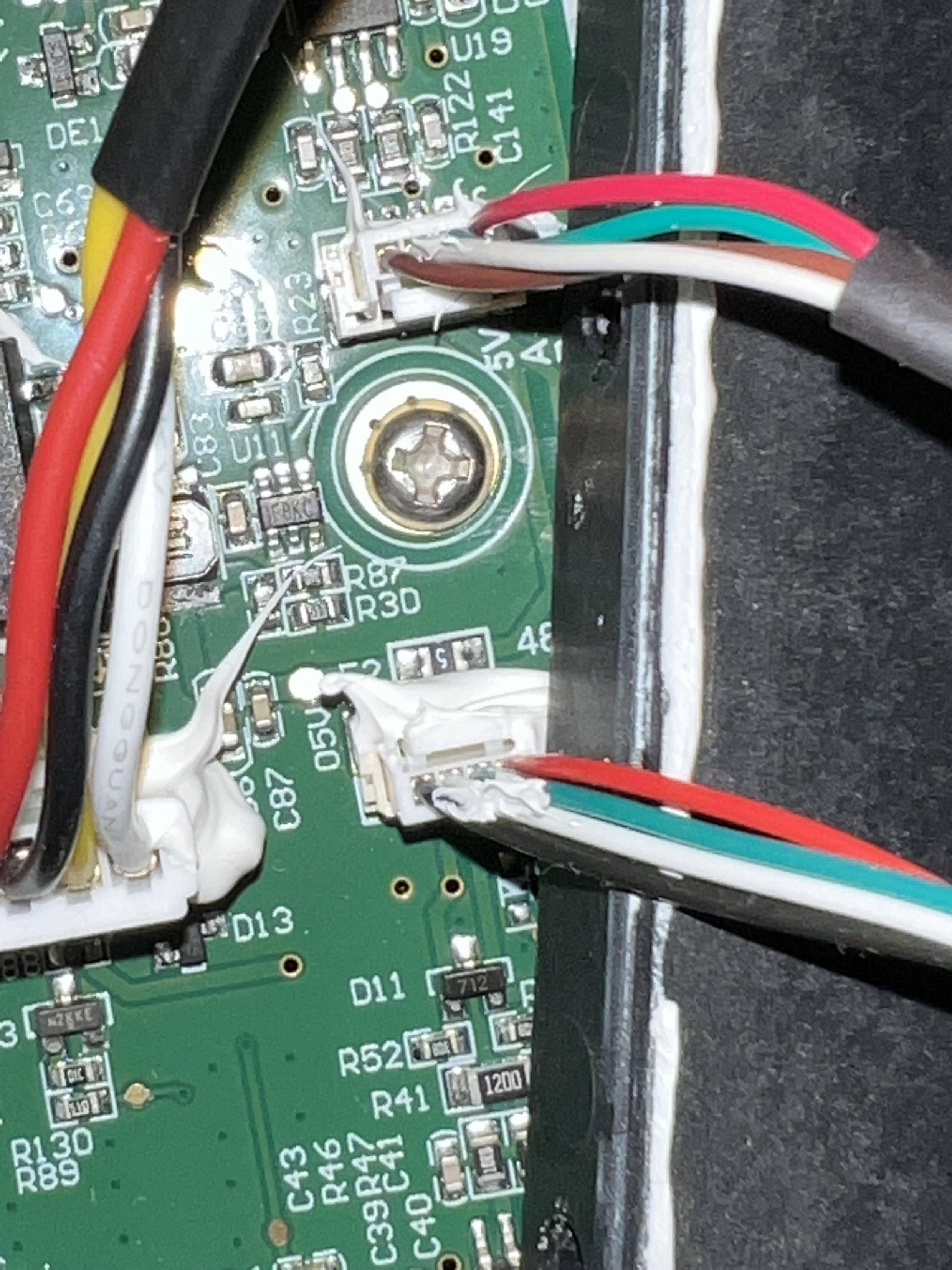
To guide myself, I opened the device to see the PCB, which seems to indicate that the physical layer is RS485 (it says RS485 on the board right next to the connector!). There's 4 wires: one ground, one 5V and an A and B labeled wires.
A nearby component on the PCB is this thing which I believe is a System-on-a-Chip? Googling for "sh6mdbt40" and it seems to support SPI, I2C and UART for serial communication. As far as I can understand from some googling, UART is the only one of those that would work over RS485, so I've been assuming that the communication is probably UART over RS485. (I don't really know what I'm doing or if what I'm saying makes any sense)
I bought an oscilloscope and connected to it. The voltage seems to be 5V and the signal lines are inverse of each other when I look at lines A and B. However from reading about UART, I assume the waveform would be shorter (1 start bit, up to 8 data bits, 1 parity bits, up to 2 stop bits) than what I'm seeing. As in, there would be maybe up to 12 changes of "state" in the waveform. But I'm counting ~64 edges.
I believe the smallest features are 25µs wide (I measured ~75µs across 3 small features).
Does this mean a baud rate of 40,000?
It seems like the message is about 5ms wide:
And that messages are sent every 120ms:
How should I approach this problem? Is there a sort of basic set of facts I'm missing, and a decision tree I could use, to guide my discovery here? What does this waveform looks like it would be?


