6
\$\begingroup\$

If a microcontroller circuit is powered from a floating 3.3 V supply, what is a safe way to use an external instrument such as a signal generator to provide a square wave into the microcontroller's clock input? I'd like to be able to do this as a diagnostic and debugging method.

I connected a sig-gen (the wavegen feature of a Keysight EDUX1052G oscilloscope) to the GND and clock-input of the microcontroller, setting up the sig-gen to produce a 10 MHz square wave (0 V low level to 3.3 V high level, into a high-impedance load.) When the microcontroller's floating power supply is powered down (while the sig-gen still runs,) I noticed that the circuit has some continued sporadic activity. Turning off the sig-gen, too, stops this activity.

It's clear that the sig-gen is partially powering the microcontroller through its clock input and GND. This worried me, so I turned it off immediately.

Given that the sig-gen and the floating PSU have a common GND, am I likely to damage my microcontroller when the sig-gen is on while the PSU is off?

What's a better way to do this?

I suspect this might be immaterial, but the microcontroller in question is a Parallax Propeller P8X32A, which is normally operated at 3.3 V. I imagine its clock input is similar in nature to that of most other microcontollers.

Manual and Datasheet

\$\endgroup\$
5
  • \$\begingroup\$ Large resistor in series with the clock, so that no significant current can flow? \$\endgroup\$ Commented Oct 18, 2022 at 20:14
  • 1
    \$\begingroup\$ You can commonly supply a clock through an RC high-pass filter (a DC blocking capacitor, with a resistor to set the DC bias on the clock-receiving side) if two components that need to be synchronized don't share a ground. I've done this several times to use buck converter controllers as inverting controllers, for instance. \$\endgroup\$
    – Hearth
    Commented Oct 18, 2022 at 20:28
  • \$\begingroup\$ @Hearth how did you avoid the floating ground to oscillate with the presumably highly varying ground currents of a buck converter, thus making the voltage between the device ground and the capacitor "output side" extremely noisy? \$\endgroup\$ Commented Oct 18, 2022 at 21:17
  • \$\begingroup\$ @MarcusMüller Heavy filtering. It helps that the interference is all synchronized to the clock as well. It's still a pretty noisy output (not too noisy for the application though), but the IC itself works. Probably would be better to do with a comparator next time I have to do something like that, though. \$\endgroup\$
    – Hearth
    Commented Oct 19, 2022 at 4:13
  • \$\begingroup\$ " the sig-gen and the floating PSU have a common GND". So, it's not really floating, \$\endgroup\$
    – John Doty
    Commented Oct 19, 2022 at 13:07

3 Answers 3

8
\$\begingroup\$

As Justme says in their answer, you shall not power an input to an unpowered IC; you'll find a table "absolute maximum ratings" in the datasheet which tells you no pin shall ever be more than 0.3 V below Vss or above Vdd. And, if you don't power the MCU, how are you going to allow that to be true?

A simple solution would be using an optocoupler, supplied from the same Vdd, to couple in the external clock: Without Vdd, it doesn't produce any output voltage. You get galvanic isolation – you don't even have to connect the grounds.

Also, an expensive solution that eats power. Other than that, you can AC-couple in – a capacitor will pass through AC even if the reference potentials on both sides are different. All you need to achieve is that the floating ground is "stable" relative to the signal generator's ground. A megaohm resistance might be sufficient for that (depending on what might be pulling said ground around) but it will technically break the "floating".

There's also RF-rated signal transformers, which would work. However, cost. Also, you might want to consider whether throwing in a second, cheaper microcontroller on the same ground just as a debugger might make sense. I honestly don't know your use case for the Propeller and your MCU experience, though, so this might be way more hassle than it's worth. (Especially since, as original as the Propeller's architecture is, for half the price of one of these chips you get dual-core 32 bit ARM microcontrollers. The 8-fold true parallelism sounds great, until you realize that access to (far too little) RAM and peripherals goes through a shared bus… the same issue any manycore architecture ever had; it's hard to exploit true parallelism, and it's easy to get yourself to a point where you content for resources. I really like the idea of the interrupt-free design, though.).

But the honestly minimal, easiest way would simply to not switch on the clock generator before you power the MCU.

\$\endgroup\$
8
  • \$\begingroup\$ On top of that, it is a non-pipelined RISC architecture, and it runs a bytecode interpreter instead of running the code natively. \$\endgroup\$
    – Oskar Skog
    Commented Oct 19, 2022 at 4:38
  • 1
    \$\begingroup\$ Even simpler and cheaper solution than ones proposed here would just be a logic buffer which can accept an input signal even if unpowered and supply it from MCU supply. \$\endgroup\$
    – Justme
    Commented Oct 19, 2022 at 8:40
  • 1
    \$\begingroup\$ @Marcus, I'm using the Propeller as a multi-channel square wave frequency generator with 16 outputs, all at different arbitrary frequencies, each derived from the original input via NCOs. The input is a GPSDO which conveniently spits out a highly stable and precise 3.3 V, 10 MHz square wave (50 Ohms characteristic impedance). These 16 take zero runtime overhead to free-run, due to the way the Propeller works. The 8 CPU cores will be mostly idle apart from one core which will drive an 2x16 character LCD display and provide a link so the device can be controlled from a PC serial port terminal. \$\endgroup\$ Commented Oct 19, 2022 at 18:06
  • 2
    \$\begingroup\$ The Propeller's code is done and dusted, works as intended when using simple local oscillators. It's just this tricky hurdle to jump over and I'm done. I don't have control over the input signal at all though, so I can't simply switch it off. If I did it would take 30 minutes to re-stabilise and ruin everything. You're right though. This chip is so bizarre it's very difficult to find compelling applications for. This task, though, is almost ideal for the Propeller. \$\endgroup\$ Commented Oct 19, 2022 at 18:15
  • 1
    \$\begingroup\$ It's not that bizarre, honestly, to have 8 relatively autonomous cores. Sure, the round-robin arbiter is special, but it's an exercise in determinism. So, I really do like it. \$\endgroup\$ Commented Oct 19, 2022 at 18:16
8
\$\begingroup\$

It does not matter if the supply is floating or not.

What matters is that you can't (generally) feed voltages to pins of unpowered MCU.

Don't turn MCU power off while feeding it with clock, and don't turn clock on while MCU has no power.

A simple logic buffer which can accept signal while unpowered can be used if it is necessary. No need for expensive or power hungry optocouplers.

\$\endgroup\$
5
  • \$\begingroup\$ I tried to use a 2n2222 transistor in an emitter follower configuration (resistors: 3.3k series with the base, 47k from emitter to GND). This simulated well in LT Spice, but on a breadboard the resulting amplitude was perhaps 1 V pk-pk, which is too low. Can you elaborate further on buffering the signal? \$\endgroup\$ Commented Oct 19, 2022 at 17:36
  • \$\begingroup\$ Use a logic chip. Not a discrete transitor. And I have no clue how the collector was connected. \$\endgroup\$
    – Justme
    Commented Oct 19, 2022 at 17:42
  • \$\begingroup\$ I'm sorry. The collector was connected to the same 3.3 V supply as the microcontroller. Perhaps a 74HC04 would be suitable? \$\endgroup\$ Commented Oct 19, 2022 at 17:46
  • \$\begingroup\$ Out of interest, why would a discrete transistor not be a good option? I'm trying to learn why I'm going wrong. \$\endgroup\$ Commented Oct 19, 2022 at 17:53
  • \$\begingroup\$ 74HC04 will have the same problem, the input can't have voltage if it has no supply voltage. Look for some other than HC type which can handle having input signal while unpowered. The problem with a single discrete transistor is that it takes so much design effort to make it work even at 1 MHz that it is just so difficult to make it work at 10 MHz you don't even want to consider that option because simpler known to work solutions exist. \$\endgroup\$
    – Justme
    Commented Oct 19, 2022 at 18:04
1
\$\begingroup\$

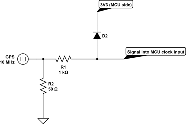
You could use a diode to shunt the signal to the supply for the MCU. This would impose a load on your GPS device's output, so you'd likely also need a current limiting resistor (R1 below). Often GPS devices with outputs like this are designed to drive into a 50 Ohm termination (R2), but you should check the datasheet for your device for the details.

schematic

simulate this circuit – Schematic created using CircuitLab

When the MCU is powered off, the signal is gently shunted to the inactive 3V3 rail. When the MCU is powered on, the diode does nothing (because it is reverse biased when the square wave is at 0V and not biased at all when at 3V3).

A schottky diode would probably be best, for its fast switching and low forward voltage.

\$\endgroup\$

Your Answer

By clicking “Post Your Answer”, you agree to our terms of service and acknowledge you have read our privacy policy.

Not the answer you're looking for? Browse other questions tagged or ask your own question.