I have some custom linear force probes I need to be able to control for a lab experiment. They're essentially just a big coil combined with a spring that deflects up or down based on the voltage put across them. Negative voltages deflect up, positive ones deflect down, and I need a range of about +-1V
I am using an Arduino Due as a DAC which can output arbitrary signals at the wavelengths (5-40 Hz) and amplitudes I need. While this goes between 0.55 and 2.75 V, it should be trivial to get a 1.65V reference voltage for the motor, so it effectively oscillates between +-1.1V.
The problem is getting enough current into the probes; my DAC can only put out about 20 mA, not enough to drive it quickly and effectively when there's any resistance.
I've tried using power op amps (which can output between 500mA to 1 A, depending on model), but have met with some issues.
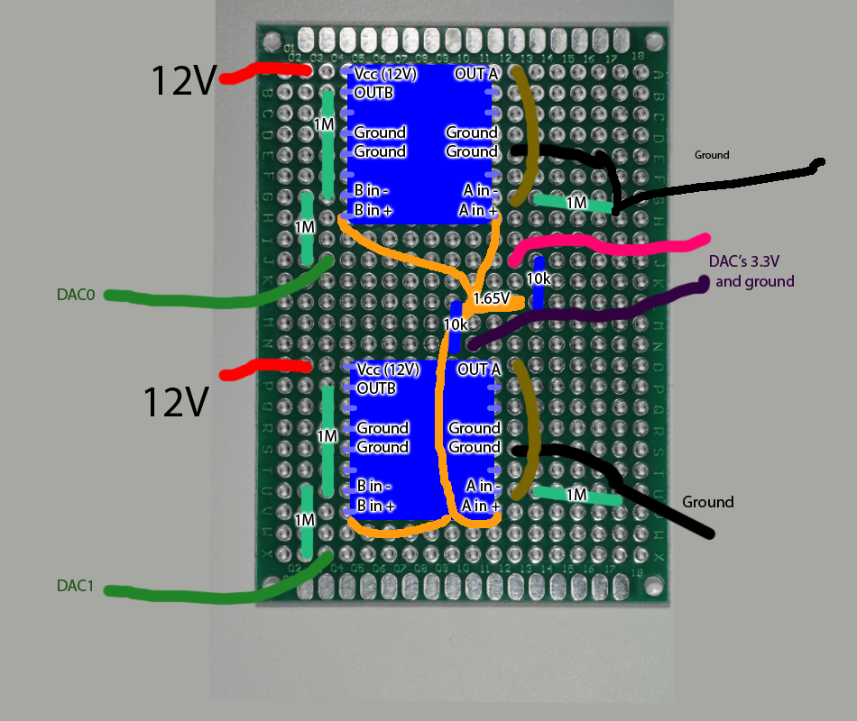
I initially started with standard plainjane boring unity-gain inverting amplifier circuit, using two two-sided op amps. Opamp A inputs DAC0 on the left side, and reference A (1.65V) on the right side. Opamp B is laid out the same way, with DAC1 and reference B(1.65V) as inputs.
While this works when a single DAC channel is running, if I run both channels simultaneously, there's odd crosstalk. The top op amp's should output DAC0, but actually outputs roughly (1* DAC0_in -0.35*DAC1_in), while the bottom op amp actually outputs (1 * DAC1_in -0.35*DAC0_in).
I tried fixing this in software, but in practice the 0.35 coefficient seems to vary from time to time, and is at least somewhat frequency-dependent, so for anything other than pure sine wave outputs at a predetermined frequency it's not a viable solution.
Things I think I've eliminated as causes
- Induction currents from the motors acting as antennae - the op amps still crosstalk even with motors detached
- Op amps pulling enough current to drop rail voltages - op amps were rewired to use different 12V 1A wall warts, which were placed on different outlets. This should be able to handle their rated maximum currents.
- Rail voltages being too low - rewired negative rails to the negative terminal of 9V batteries (with the positive terminal of 9V attached to ground from the respective wall wart.) -The DAC being bad and crosstalking on its own - hooking up the DAC output directly to my scope without passing through the op amps results in no crosstalk.
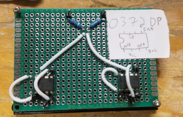
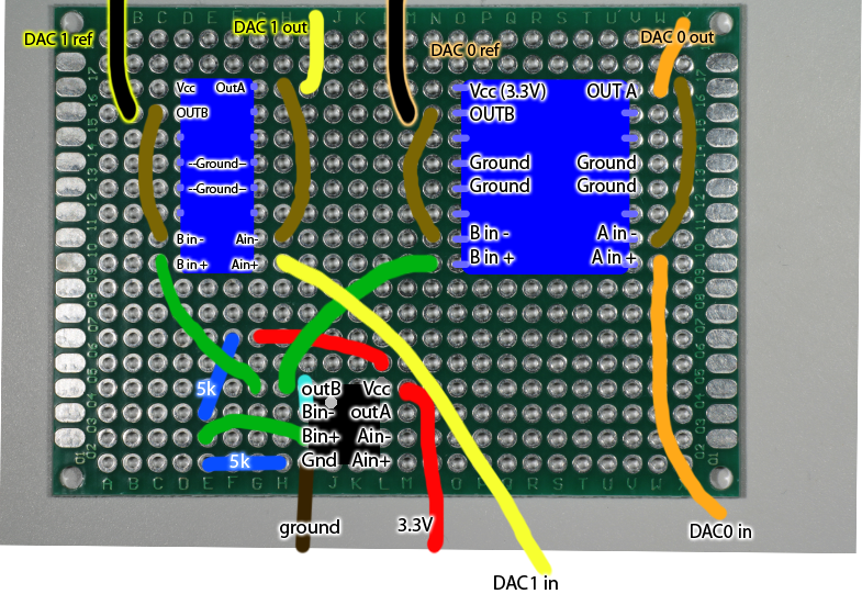
For the next few attempts, I decided to go simpler and make the simplest possible buffer circuit (connecting V- to Vout). This just flat out doesn't work, at all, with any of the power op amps I've tried. A couple examples of nonfunctional circuits.

 All my signals, from 0 to 3.3V, end up getting output as Vcc from the top op amps.
I've tried doing some digging on why this is happening, and have applied a few voodoo debugging fixes.
- Dropping the negative rail to -9V with a battery (which should prevent the 'near rail voltages cause maximum output problem)
- using different models of op amp
- using capacitors to smooth out rails and reference voltage
- sticking 1M resistors between the inputs and ground
But I'm still getting nowhere. My guess is that they just don't like having low impedance feedback.
Frankly I'm a bit stumped, and I'm starting to think I'm yak-shaving and that there has to be a better way (or off-the-shelf-component) to do this.
I think my next option is to buy more components and make a two-stage op-amp circuit, starting with a rail-to-rail op amp to offset my reference and signal by +6V (so they run 6-9.3V), run that through the powered op amp in an inverting circuit, and run both motor using voltages which are elevated above ground. But, given how I clearly am not understanding this system, there's no guarantee that will work either.
Is there a better option that I'm just not seeing? I think my big complication is that I have a lot more experience working with op amps in their ideal ranges, and running up against a circuit that works perfectly in multisim and doesn't work on the board is stumping me.
If there were just an inexpensive buffer amplifier I could use, or a cheap higher-current DAC or whatever, that would be great, but I haven't been able to find one.
Or if there were an off-the-shelf, easy to control linear motor which can be controlled to move to arbitrary points in a +- 300 micron range at 25 Hz. Unfortunately that's super high amplitude and low frequency for the usual piezo elements.
I hope this is just a dumb question and there's a $5 part I don't know about, or six cent resistor I need to solder in that'll fix everything.

