I have a preamplifier based on an OPA1611 that I wanted to characterize. The amplifier is in a fully enclosed and earthed metal chassis, which has an AC-DC converter in it. The mains cabling goes directly from the connector into the converter's screw terminals via ~5 cm of cabling. The AC "compartment" in the chassis is separated from the remaining low voltage circuit via an aluminum mounting plate (which provides no magn. shielding against low frequency). On the low voltage board, there are some DC/DC converters. The amplifier circuit is eventually supplied with +/-14V after going through a lot of active and passive filtering, both for common-mode with respect to Earth and differential mode. The same can be said about the reference and supply voltage for the ADC. The ADC runs continuously, sampling at 125 kHz. For the data below, blocks of 250 samples are averaged and passed on every 2 ms (sampling rate effectively being 500 Hz). Then, these block averages are collected for a few seconds. The harmonic content doesn't change if the block size is changed.
The preamp input is shorted using on-board switches; the shorting trace encloses a loop of maybe 1 cm². I am taking values from the ADC and FFT them.
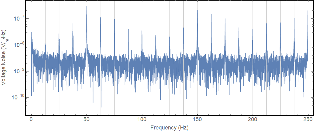
I expected to see the usual picture: the amplifier noise, overlaid with a couple of mains harmonics, but instead I found that all the mains harmonics have sidebands with a distance of \$f_{mains}/4=\$12.5 Hz.
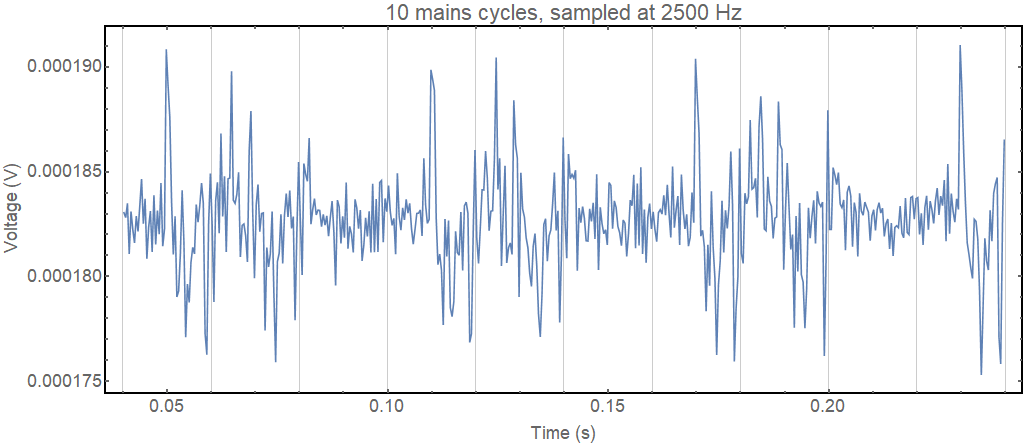
A little while later, I tried to capture a faster time trace to have a look at the waveform and obtained this:
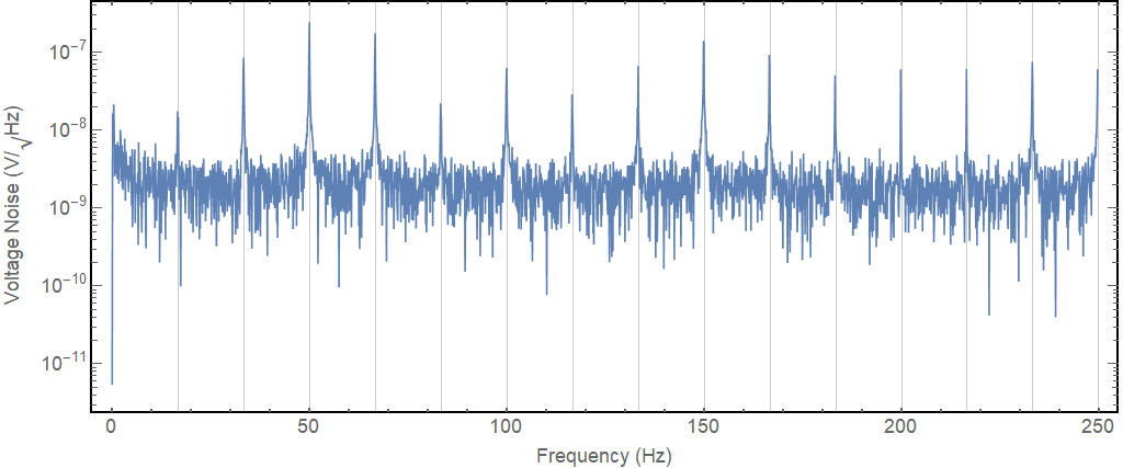
Strangely, the waveform now repeats every three mains cycles. And the FFT confirms as much:
The only thing in the chassis that might do something with mains synchronisation is the AC-DC converter. Other than that, I would suspect that subharmonic noise can only come from mains voltage contamination
Is it likely that the AC-DC-converter (e.g. its PFC) can create sub harmonic noise ? If not, what to look for in the environment (an office with a PC and LED lighting)?


Then, these block averages are collected for a few seconds.One "block" average is one data point in the final data vector, which contains many such averages. \$\endgroup\$