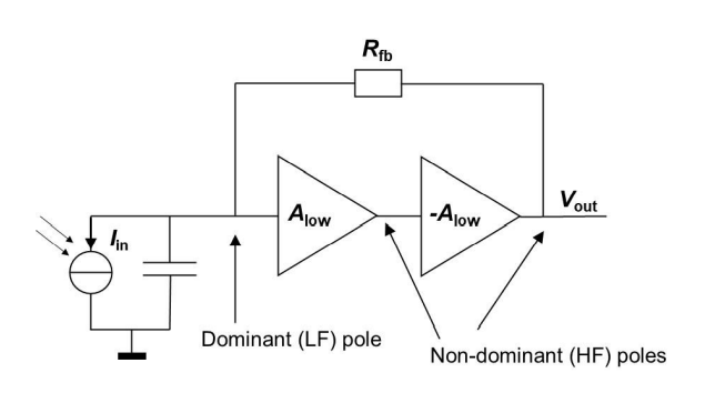
I am trying to build a transimpedance amplifier consisting of two stages driven by a photodiode with a parasitic capacitance of 11 pF (see below). The GBW of each amplifier is 100 MHz and the target frequency is 1.5-3 MHz.
The purpose of the assignment was to calculate the value of the gain and the value of the feedback resistor such that the phase margin was acceptable (not unstable and no/limited amount of oscillating).
As I was not familiar enough with phase margin and there were no circuits online of this configuration with explanation, I chose to let the non-dominant pole be at 10 MHz and then changed the dominant pole created by the parasitic capacitance and the feedback resistor to be at a frequency such that the two poles would result in 0 dB gain at 3 MHz (and a bit of margin). This answer was deemed as valid but not proper.
What would be the correct way to get a stable circuit? Note: We were only allowed to change Rfb and the gain of the op-amps.

