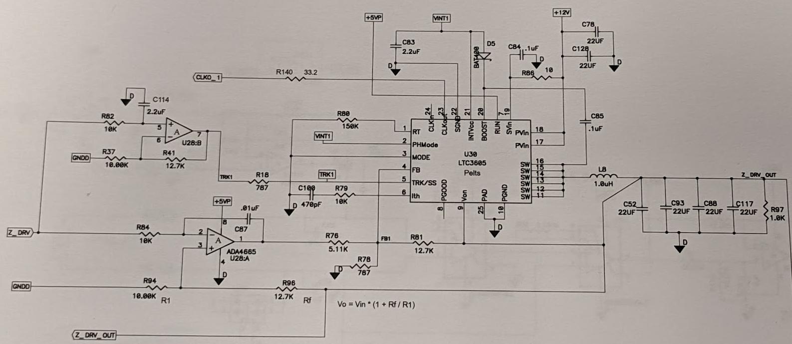
Here is the circuit under analysis:
A few questions:
Z_DRV is a signal from a DAC. From what I can understand, this signal is amplified by U28:B. This in turn causes the output of the switcher IC to track the voltage on the TRK/SS pin up until the feedback voltage reaches its regulation voltage (on pin 5). Why would someone want to have the switcher track? I understand that it can be used for soft starting but I am not familiar with what else this type of setup can be used for.
The same DAC signal goes to U28:A. Typically I have seen some circuits where a FET is placed with another resistor on the feedback pin in order to quickly change the output voltage. But here, it is an op-amp with its feedback path along with the feedback path of the switcher. What exactly are they trying to achieve here? A more advanced startup sequence?
If the two above questions are commonplace, is there an app note source so that I may get better informed on these techniques and circuits?

