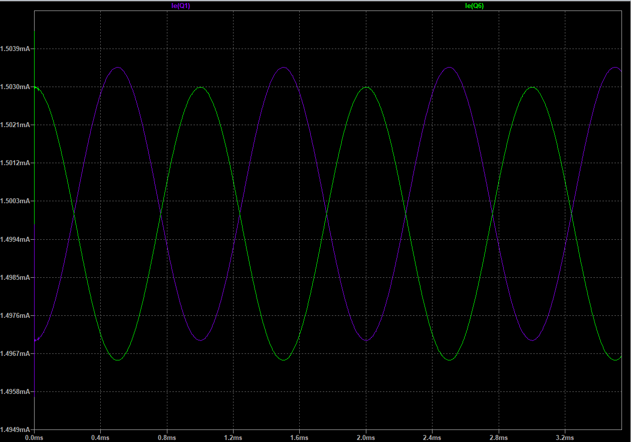
The current is needed to charge C2 to the desired output voltage.
Q3 and C2 are a so-called Miller integrator, which is a circuit that integrates a current at its input into a voltage at its output. If you inject a current into the input of the Miller integrator, the output voltage will decrease (if the current flows "into" the integrator) or increase (if it flows "out of" the integrator). If you don't inject any current, the output voltage will stay steady.
The faster you want to change the output voltage, the more current you have to push into the Miller integrator. (Slew rate is proportional to input current. It's just charging and discharging the Miller capacitor, C2.)
Your differential input stage converts a voltage difference into an output current. This output current gets fed into the Miller integrator, which then produces the desired output voltage. The faster you want to change the overall circuit's output voltage, the more current the differential input stage has to push into the Miller integrator, which is why current balance (and therefore linearity) degrades at high slew rates.
You can try to decrease the value of C2 if you want your amplifier to be faster and more linear. Note, however, that this pushes the amplifier closer to instability. C2 is needed to slow the amplifier down enough so that it doesn't start to oscillate on its own. If you use the amplifier in a configuration with gain (i.e. a noninverting amplifier configuration), you can shrink C2 almost proportionally to the overall circuit's high-frequency (AC) gain. I.e. if you build a gain=10 stage with this amp, you could shrink C2 to 100pF (best case) or 220pF (likely practical value), depending on the frequency response of the feedback network.
In a practical working circuit, you will also have to insert resistors at the emitters of Q2 and Q5 to compensate for the discrete transistors' lack of perfect matching. These resistors should drop roughly 100mV when the differential stage is in current balance, which translates to a value of 68 Ohms at the 3mA bias current you're running through the differential pair. (The reasoning behind the 100mV drop is this: A silicon transistor's collector current increases 10-fold when the base-emitter voltage increases by 60mV, so 60mV would be ideal. Add in another 40mV safety margin to account for offset voltage and temperature differences between the transistors, and you arrive at 100mV.)


