I'm planning to create a circuit to measure inductance by creating a stable sinusoidal oscillator out of it with a known value capacitor. Then measuring the oscillator frequency accurately with an oscilloscope should accurately tell the inductance value, even if the inductor has huge resistance too, assuming the capacitor value is known accurately (so the capacitor in practice has to be measured with a multimeter before using it in the circuit).
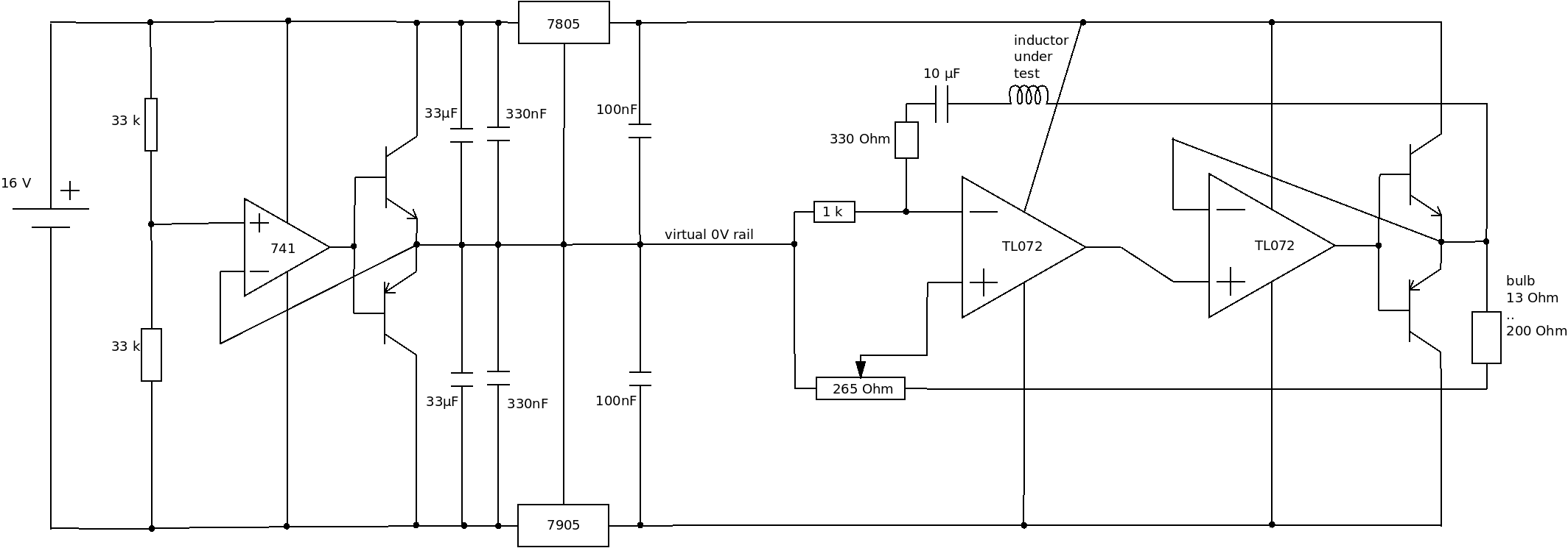
So I designed a circuit that I think should start oscillating stably:
The left side contains the power supply: from single-sided 16 volts (negative not grounded) to dual-sided +5V / -5V with a virtual 0 V rail. I already created the power supply part on a breadboard and measured exactly +5V and -5V, and I think it the virtual 0V rail should both be able to source and sink current. However, I'm not sure if this kind of power supply creates a stable enough 0V rail. At least the 33 µF capacitors and 3V regulator dropout should offer some time for the 741 to react when changing from current source to sink.
An alternative to the voltage splitter would be a capacitor pump, which would allow high dual-sided output voltages with not so much input voltage.
The right side of the circuit contains a circuit that I think should start oscillating. My theory is that the op-amp should amplify the oscillation only if the negative and positive inputs are in phase, which means that the capacitive reactance of 10 µF capacitor cancels the inductance reactance of the inductor under test since the positive input has a real-valued voltage divider and to get inputs in phase, the negative input too must have real-valued voltage divider. So negative side has 1000 / 1330 = 0.75188 voltage divider ratio which the positive side has to match.
The positive side has a voltage divider ratio that is given by a potentiometer and light bulb (1 watt automotive voltage bulb). The idea is that as current starts to flow, the light bulb heats, which increases its resistance, which decreases the voltage divider ratio on the positive side. I measured the bulb to be about 13 Ohms when current is small, and calculated that to be 1 watt at 14 volt automotive voltages, it needs to be about 200 Ohms at 70 mA current.
The positive side ratio therefore can be adjusted from as high as 265/(265+13) = 0.95 with cold bulb which should be enough to start oscillation, to a ratio as low as 0 even if the bulb is hot at 200 Ohms.
Since the light bulb may require larger current than TL072 can supply, I put a secondary TL072 on the circuit to drive a push-pull transistor pair. The secondary TL072 is obviously on the same chip as the first. (Actually, is that secondary TL072 necessary or could I just route the output of the first TL072 to the connected bases of the push-pull pair?)
Unless the circuit has some major flaw, I think it should work, provided that stable oscillation can be achieved with only at most ~2-3 volt amplitude (since closer to supply voltage might cause clipping in the op-amp). How easy this is, will be determined by how big resistance change the bulb has at 2-3 volt amplitude (1.4 - 2.1 volts RMS). If stable oscillation is too tricky, it may be necessary to change 16 volt input to 24 volt input, and to switch 7805 and 7905 into 7809 and 7909, to get larger oscillation amplitudes.
Does the oscillator look like it would work? Or is my theory incorrect about self-amplification happening only when both negative and positive side have real voltage divider ratio, until the bulb has heated so much that voltage divider ratios self-stabilize the oscillation amplitude?
The inductance values would be between 1 µH and 1000 µH, so frequency would be between 1.6 kHz - 50 kHz. The 10 µF capacitor is a bipolar polyester capacitor and not an electrolytic one.
The transistors are BC546 and BC556 since 100 mA currents are enough.

