0
\$\begingroup\$

I'm trying to design a controller for a boost converter by the "shaping loop gain" method as in the Fundamentals of Power Electronics textbook by Ericson and Maksimovic.

I see that there is a RHP Zero, which if we have just a unity feedback system makes it unstable, so we need a controller of say Gc transfer function.

Now I chose the desired crossover frequency, etc. for Gc, but unless I add an RHP pole to cancel out the RHP zero, the system is always going to be unstable. Can I have my controller to be just a lag compensator?

EDIT 1: This is my loop gain when there is no controller, only the plant transfer function is being plotted :- enter image description here
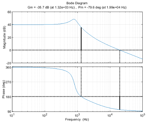
Now I want this to be operating at 20 kHz switching frequency, so I need to move the gain crossover frequency, and I set it to 3 kHz. To do this, at present the plant gain at 3 kHz is 20.23 dB, so my compensator should have a -20.23 dB = 0.097 gain. I set my pole at

$$ \dfrac{fp_0}{3000} = 0.097, fp_0 = 292.16 Hz $$

So my compensator is $$G_c = \dfrac{2\pi(292.16)}{s} $$

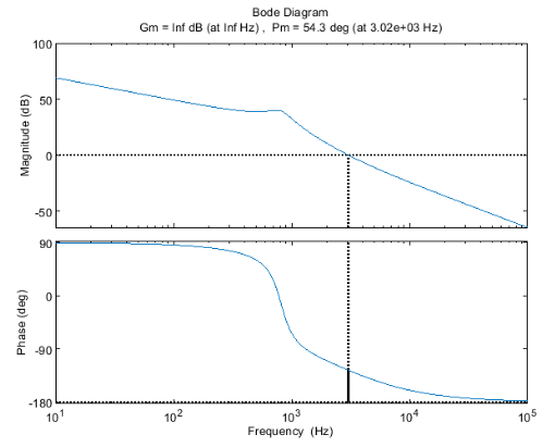
While this does move my GCF to 3 kHz, I get a weird gain margin which I don't understand how to proceed with the design.

enter image description here

\$\endgroup\$
3
  • \$\begingroup\$ No, you can't just cancel the RHP zero with a RHP pole. You have to close your loop at a bandwidth significantly lower than the RHP zero frequency. \$\endgroup\$
    – John D
    Commented Nov 22, 2022 at 23:04
  • \$\begingroup\$ @JohnD But even a unity feedback system with RHPZ will give instability, and as long as that RHPZ remains in the system, its closed loop will always be unstable right? \$\endgroup\$
    – SM32
    Commented Nov 22, 2022 at 23:10
  • 1
    \$\begingroup\$ No, incorrect. Every boost/flyback converter has a RHPZ. If it's far enough away from your loop bandwidth the phase contribution won't cause your loop to be unstable. You can't add a RHP pole to cancel it, THAT will make it unstable. \$\endgroup\$
    – John D
    Commented Nov 22, 2022 at 23:15

1 Answer 1

3
\$\begingroup\$

The two-step conversion process in a boost or a buck-boost converter introduces a delay modeled by a right-half-plane zero or RHPZ. When a sudden load step occurs, the loop reacts by increasing the duty ratio \$d\$ in an attempt to increase the energy stored in the inductor. However, this cannot happen instantaneously and the reaction time depends on the applied V-s and the inductance value. See this paper I wrote some time ago.

Considering the average current in the diode defined as \$I_d=I_L(1-d)\$, you see that if the loop instructs \$d\$ to increase, then (1-\$d\$) goes does down and counteracts the effect of increasing the average inductor current cycle-by-cycle. Unless you purposely slow down the loop reaction speed and give more time for the inductor current to build up. In other terms, despite a fast change in the output current, the change in the duty ratio will not be fast, allowing the energy to build up in the inductor while (1-\$d\$) slowly reduces.

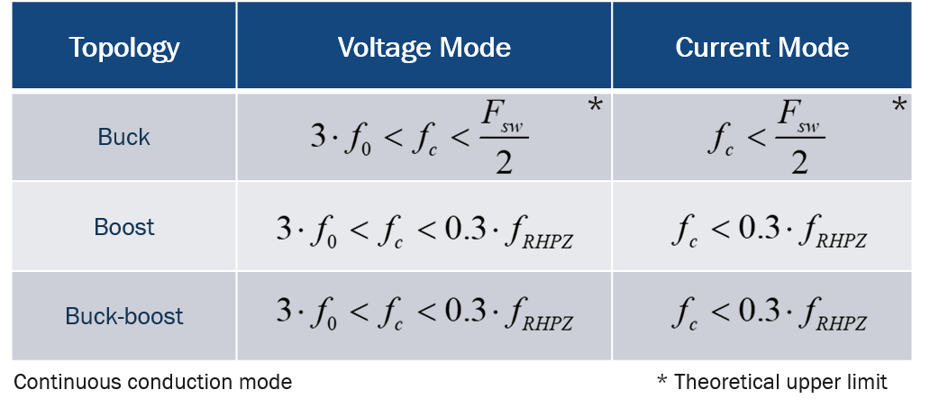
As a summary, you have to slow down the loop by limiting the crossover frequency. You do that by first determining the lowest position of the RHPZ and then choosing a crossover frequency around 20-25% of this lowest position. If you try to push crossover higher, then phase margin may reduce and instability is likely to occur. Below is a picture excerpted from my APEC 2021 seminar showing that the choice of crossover is intimately linked to the structure and not just 1/5th or 1/10th of \$F_{sw}\$ as I have often seen:

enter image description here

To stabilize your boost converter, you can use analytical analysis as I did in my last book on transfer functions, use an averaged model or go to the bench and build a prototype. Another option consists of using a piece-wise linear (PWL) simulator such as SIMPLIS and extract the control-to-output transfer function from a switching circuit. This is what I propose with my 80+ free ready-made templates you can download from my webpage:

enter image description here

Please note that the RHP zero exists at the same location regardless of the control mode, voltage- or current-mode control. There has been many attempts to get rid of the RHPZ by using specific scheme such a leading-edge modulation - see this paper for instance - but I am not sure if it has ever been practically implemented in volume applications. And no, you don't want to insert a RHP pole in a system to cancel a RHP zero.

\$\endgroup\$
3
  • \$\begingroup\$ Thank you for your reply! I have been looking at your other book on control loops design and I have a doubt: following it, I am getting infinite gain margin at infinite Hz from MATLAB, although I like my PM and where the crossover frequency is. How to fix this? \$\endgroup\$
    – SM32
    Commented Nov 25, 2022 at 19:01
  • \$\begingroup\$ @SM32, hi, the control-to-output transfer function of the boost operated in voltage-mode is a second-order system in CCM (also in DCM but heavily damped). You should see the gain naturally rolling off after the double-pole peak while the phase hits -180°. Did you try the boost example from my templates, just to compare with your Matlab expression? \$\endgroup\$ Commented Nov 26, 2022 at 8:56
  • \$\begingroup\$ I added some edits to my question, it'd be great if you could look at it \$\endgroup\$
    – SM32
    Commented Nov 26, 2022 at 20:05

Your Answer

By clicking “Post Your Answer”, you agree to our terms of service and acknowledge you have read our privacy policy.

Not the answer you're looking for? Browse other questions tagged or ask your own question.