0
\$\begingroup\$

Specs:

5hp 16 Gallon Rigid wet/dry shop vac household type

Serial Number: 09270 R 2217

Model: WD16360 120V 10A. 60Hz

Motor: M188306380002 09241 AD U79-251200-001E01 120V 60Hz

PROBLEM SUMMARY:

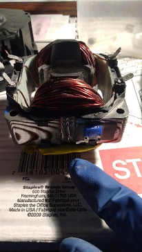
I disassembled the shop vac motor to replace the termal fuse on one of the stator windings and I don't remember if it's the black cable or the white cable that goes to the start (auxiliary) winding.

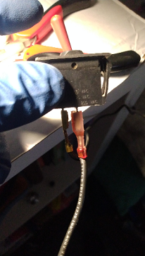
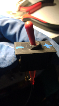
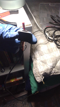
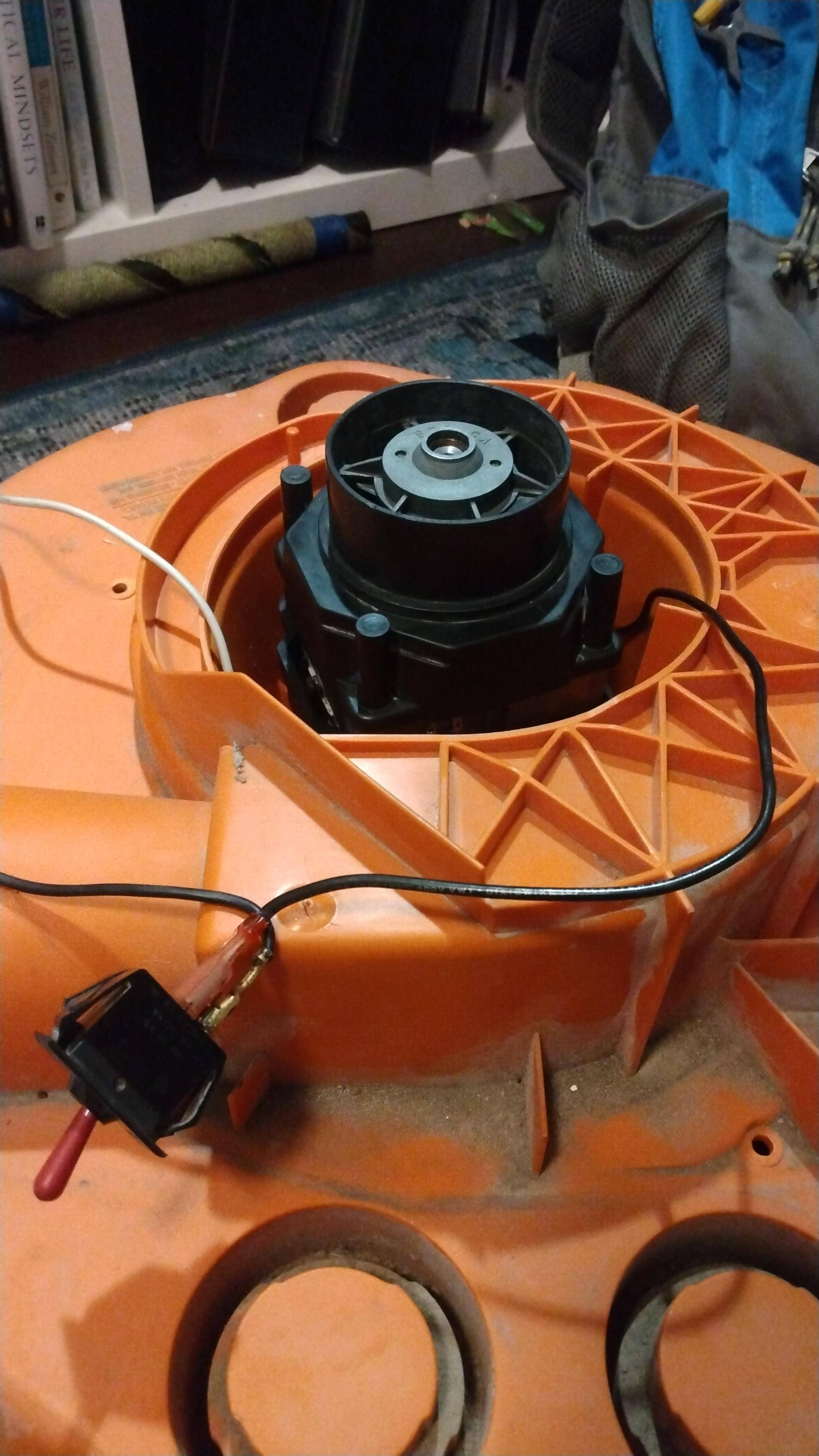
The black cable goes from the centrifugal switch (flick switch - terminal insulated with red silicone sleeve to indicate that it's power?) to one of the terminals on the stator armature.

The white cable goes from the power supply cable directly to one of the terminals on the stator armature.

DETAILS AND RESEARCH: I measured the resistance at both windings to define the start winding. Both windings gave me a constant but no difference. e.i., steady 0.00 reading.

I figured that the flick switch would turn off the black cable (terminal insulated with red silicone sleeve at flick switch) and keep supplying 120v power to the run winding via the white cable once the engine was up to speed (typically 75%-80% of full run speed). [please correct me if my theory is wrong] - thanks.

Hence, this would allow me to figure out which cable goes where.

However, that didn't work out so I had to go down a different route.

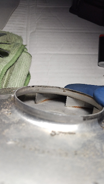
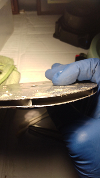
A practical thing that I did was to look at the blower wheel and noticed that the curved spines angle counter clockwise. So they move air in that direction?

Is this a good guide to connect the wires correctly? based on the direction of the spines on the blower wheel.

Once I connect the terminals and the engine starts spinning counter clockwise the brushes start to spark but the spark doesn't go around the rotor or anything like that. I did notice a bit of chipping on the tips of the brushes after running the engine without it being fastened to the vac body and the motor will slip out of my hands if I don't hold it tight!

Is it normal for the brushes to spark a bit and for the brushed to chip if the armature housing is not stabilized in place?

Another rational thing that I did was to figure that the run winding would need the temp fuse after the start winding had turned off. Is the winding with the temp fuse the run winding?

I couldn't find any diagrams or guides for this engine specifically so any comments help my learning and help me know how to fix equipment correctly before I toss it. Also, I hope it helps another person out there with a similar problem.

Thanks again.

enter image description here

enter image description here

enter image description here

enter image description here

enter image description here

enter image description here

enter image description here

enter image description here

\$\endgroup\$
9
  • \$\begingroup\$ If this is a high-power motor, it might have low resistance coils. Try measuring the windings' inductance rather than resistance. \$\endgroup\$
    – Hearth
    Commented Dec 1, 2022 at 20:52
  • \$\begingroup\$ @Hearth is there a way to measure inductance just with a multimeter? thanks. \$\endgroup\$
    – LVX-001
    Commented Dec 1, 2022 at 21:43
  • \$\begingroup\$ Not without additional stuff. An LCR meter is the usual go-to tool, but you can hack something together with a multimeter, a known impedance (like a resistor), and an AC power source of some type. \$\endgroup\$
    – Hearth
    Commented Dec 1, 2022 at 22:00
  • \$\begingroup\$ You can make a useful and simple continuity/inductance tester by connecting an electromechanical buzzer and battery in series. It will make a higher pitched sound when connected to a short, and lower frequency sound with inductance. \$\endgroup\$
    – PStechPaul
    Commented Dec 1, 2022 at 22:24
  • \$\begingroup\$ @PStechPaul Based on what I understand so far. Basically, if I take this homebrew continuity/inductance tester and I connect it in series with a multimeters' leads (red lead to a power terminal on the motor stator and black lead to ground) while the motor is running, I would hear a low frequency sound on the winding that has a higher resistance or inductance (start winding during the motor's start phase if we're dealing with a induction motor) and a higher pitched sound on the winding with a lower resistance or inductance (run winding before start winding "turns off"). \$\endgroup\$
    – LVX-001
    Commented Dec 13, 2022 at 16:26

3 Answers 3

5
\$\begingroup\$

It's a universal motor with its schematic as shown below.

enter image description here

The direction of rotation will not change when the power connections are interchanged.

It will, when the brush connections are interchanged

\$\endgroup\$
2
  • \$\begingroup\$ do you know what the 4th symbol on the left represents in this diagram? AC --> switch (similar to SPST toggle switch?) --> [ ? ] --> inductor --> Motor --> inductor --> AC. Thanks \$\endgroup\$
    – LVX-001
    Commented Dec 5, 2022 at 14:28
  • 1
    \$\begingroup\$ Only five components are shown in the schematic: 1. Supply terminal 2. SPST toggle switch 3. Field winding 4. Armature 5. Field winding. \$\endgroup\$
    – vu2nan
    Commented Dec 5, 2022 at 16:51
4
\$\begingroup\$

This is a universal motor, not an induction motor. A universal motor is basically a series wound dc motor, will run on either ac or dc. The reason vacuum cleaners use universal motors is they can run at high speeds. Induction motors are limited to line frequency.

There isn't any photo of the brush holder, but it would be connected between the two stator coils. The power is connected to the other ends of the stator coils, which end gets black and which gets white doesn't matter.

Regarding direction of rotation, the impeller (blower wheel) would be a backward-curved type. If the blades angle clockwise, as you say, the impeller should rotate anti-clockwise. (There also exist forward-curved impellers; these are used in lower speed applications such as HVAC.)

To test the direction of rotation, you can apply power briefly, just long enough to get it turning. To reverse the direction, swap the terminals on the brush holder

Probably not safe from an electric shock perspective to be operating this motor while holding it in your hand. Glad to see at least you are wearing gloves in the photos.

\$\endgroup\$
1
  • \$\begingroup\$ I stand corrected. you're right. this is actually a high speed backward-curved impeller. the blades rotate counter clockwise when looking at the impeller from the bottom inside (as shown on the 2nd to last image above) and clockwise when looking at the impeller from the side ( last image). This impeller is designed to rotate clockwise when running. \$\endgroup\$
    – LVX-001
    Commented Jan 20, 2023 at 8:27
3
\$\begingroup\$

If it has stator windings as you shown the picture, and it has brushes, then surely it's a universal motor - could run on AC or DC. You can tell because they sound different. An electric lawnmower is an induction motor, it winds up to a constant speed and doesn't drop much when under load. A weed eater, vacuum cleaner or angle grinder has a DC motor and changes speed a lot under load.

On a vacuum cleaner it will very likely be a series connected motor. It's not safe to run these at full voltage with no load, so be careful when you test it.
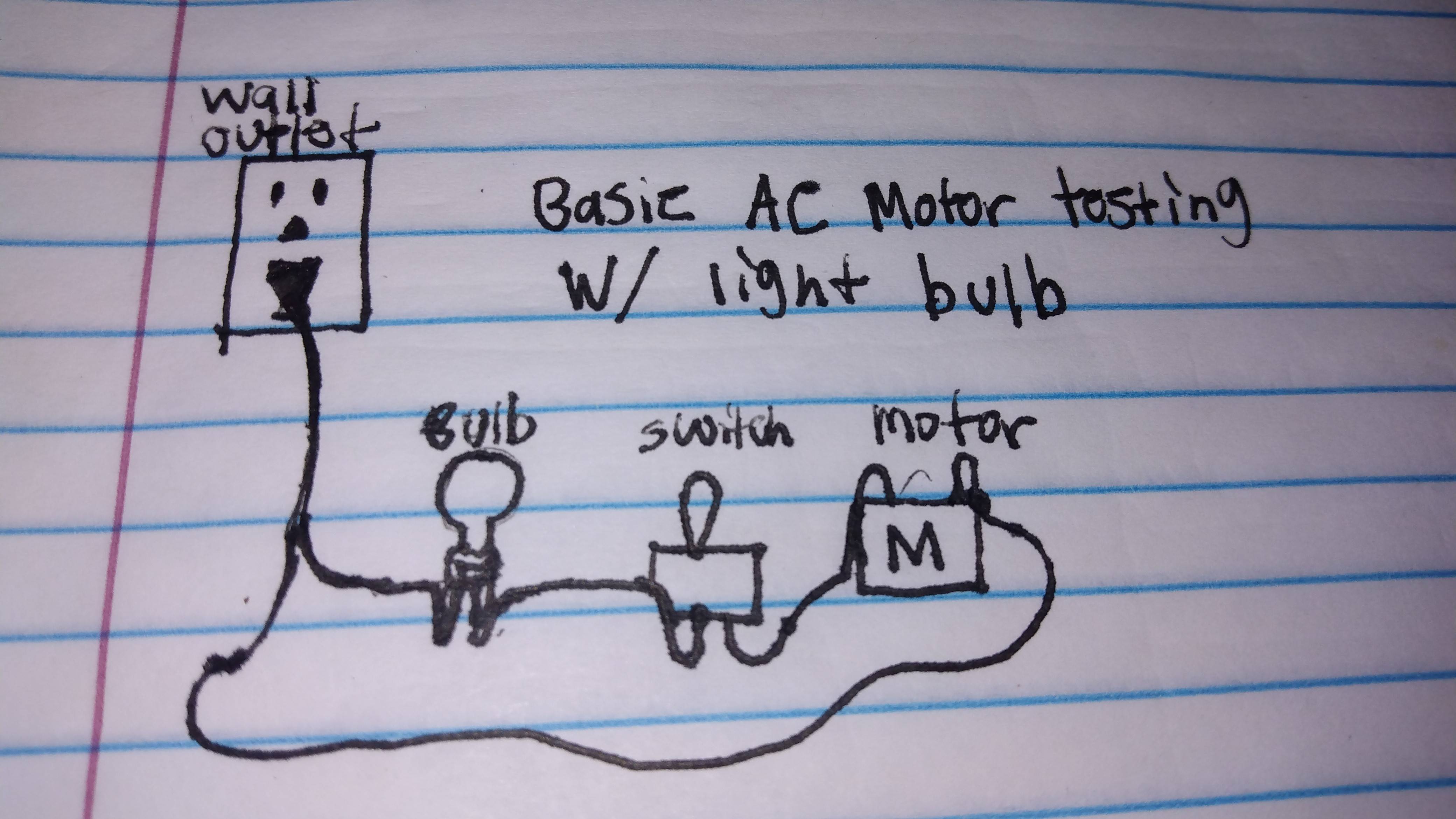
It's normal for brushes to spark a little. If the motor itself is fully assembled (with a bearing, properly mounted, on each end), and turning the right way, it won't damage the brushes to test it without the fan. But because of the overspeed problem, rather test it in series with an incandescent light bulb or other resistor of that sort of value. Or use 12 V DC.

I think you're asking about the two stator windings - these would normally be in series, such that they produce a field that goes in the same direction, making a North and a South pole facing the rotor. i.e. in your first photo, the current in both windings should go clockwise as you look at it. So either follow the wires to check which way they go, or experiment. It won't run at all if one is reversed.

The direction is also determined by the relative polarity of the brushes and the stator windings. So you need to first connect the two stator windings in series correctly, and then them in series with the brushes. It doesn't matter which side goes to hot and to neutral, except that the (human) switch is usually on the hot side.

The direction of rotation of the fan(s) is to fling the air outwards, not scoop it towards the centre. So the blades in the moving part should turn in the way that the edge wouldn't bite your finger. Clockwise in your last photo, I think.

The thermal fuse is there to protect the motor and its owner, when it overheats - either due to a lack of cooling air or the bearings seizing. Please do replace it with a new one of the same temperature rating - otherwise you're leaving a trap to catch someone out one day. That said, the blue fuse on the outside looks like a regular overcurrent fuse. Thermal fuses have long legs so they can be soldered or crimped without overheating them by accident, and they'll be in a heat shrink tube, tied firmly against the actual windings.

\$\endgroup\$
15
  • \$\begingroup\$ hello tom, Im gonna sound like such in a noob but how would I test this motor in series with a light bulb? or what other common household resistor could I use? \$\endgroup\$
    – LVX-001
    Commented Dec 1, 2022 at 22:42
  • \$\begingroup\$ You would take a 100 W bulb, screwed into one of those adapters making it a two prong plug, and then connect in series, anywhere in the circuit, with wire and insulation tape. Be careful of course. Always use a GFCI / Earth Leakage / RCCB when doing this. \$\endgroup\$
    – tomnexus
    Commented Dec 1, 2022 at 23:53
  • \$\begingroup\$ so once I connect the lightbulb to the two prong adapter I hook up the power prong to a power source such as a battery or directly to one of the terminals on the armature using a cable (maybe 12-18 AWG?) and the ground prong to perhaps the "power" (black cable) lead going to one of the terminals on the armature. The wires coming from the two prong adapter just touching the terminals without disconnecting the white or black cables going to the armature terminals. \$\endgroup\$
    – LVX-001
    Commented Dec 2, 2022 at 18:36
  • 1
    \$\begingroup\$ I mean the whole experiment should be through GFCI - if you have a spare outlet, they usually have output terminals as well as input terminals. It's not for the lightbulb, it's to protect you if you make contact with the wires, which is quite possible with all these things connected in the open. Also try 12 volts if you have a power supply or something, it might generate enough torque to tell you which way it will turn, without any risk of shocks or mechanical chaos. \$\endgroup\$
    – tomnexus
    Commented Dec 2, 2022 at 18:56
  • 1
    \$\begingroup\$ If you're using mains power - connect everything in series. (GFCI)Hot -> lightbulb -> switch -> stator winding -> brushes -> stator winding -> (GFCI)Neutral. If you're using 12 V, leave out the lightbulb. \$\endgroup\$
    – tomnexus
    Commented Dec 2, 2022 at 18:58

Your Answer

By clicking “Post Your Answer”, you agree to our terms of service and acknowledge you have read our privacy policy.

Not the answer you're looking for? Browse other questions tagged or ask your own question.