0
\$\begingroup\$

I know that every OP Amp does have a limited capacitive load drive capability. Even if not specified, it is always a good practice to use a series isolation resistor. Anyway; when looking at an active butterworth low-pass filter, I can't use an isolation resistor: enter image description here
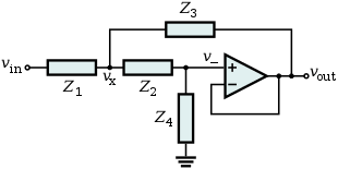
I want to realize an active filter with 1 Hz cut-off-frequency. Additional requirement is ultra low noise - therefore resistance values should be low (<20k Ohm). With Z1=Z2= 16k Ohm and a fc = 1 Hz the capacitor should be 10 µF = Z3 = Z4.

In this application, do I need to care for the max. capacitive load of the op amp as it is in the feedback loop? Can I use a 10 µF capacitor in combination with f.e. a ADA4523 Op Amp?

Thanks, Frank

\$\endgroup\$
1
  • 1
    \$\begingroup\$ Capacitors are not directly tied to the ground. So should be ok. \$\endgroup\$
    – Antonio51
    Commented Dec 6, 2022 at 20:06

2 Answers 2

3
\$\begingroup\$

The stability issues with driving a capacitive load with an op-amp have to do with a capacitive load to ground.

Basically, without feedback a typical op-amp has an output impedance of hundreds of ohms (but it can vary -- a lot). Driving a capacitive load through this resistor creates a pole that creates a phase lag, and with feedback that can make the amplifier oscillate.

You are not returning the other end of Z3 to ground -- you're returning it to the junction of Z1 and Z2. Those isolate that end of Z3 from ground, to the tune of at least \$8 \mathrm k\Omega\$. It's more complicated than that, but unless you're using an exceptionally wimpy op-amp (see below) you're fine.

I'm not sure if an op-amp even exists that would have problems with this. It would have to be designed for super low-power operation (or more weirdly, super high-voltage operation), and have an open-loop output impedance close to or more than \$8 \mathrm k\Omega\$. Basically, if the data sheet suggests that you can't drive an output impedance less than \$10 \mathrm k\Omega\$ or so then start worrying -- or multiply your impedances by enough that they start matching the resistor values in the data sheet's example circuits section.

\$\endgroup\$
2
\$\begingroup\$

Don't have ADA4523 in the database.

Will use another op-amp like ADA4062-2. Don't checked if "equivalent". (not really).
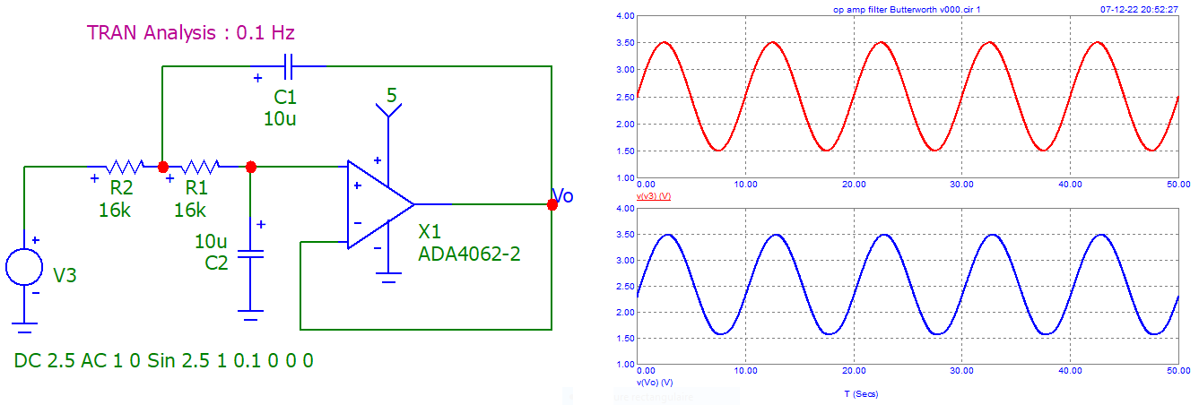
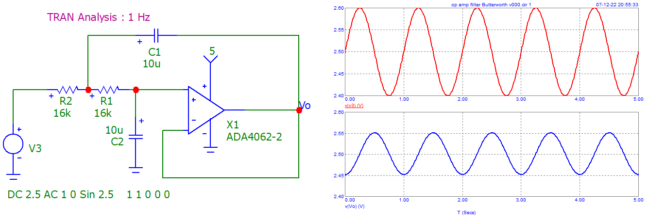
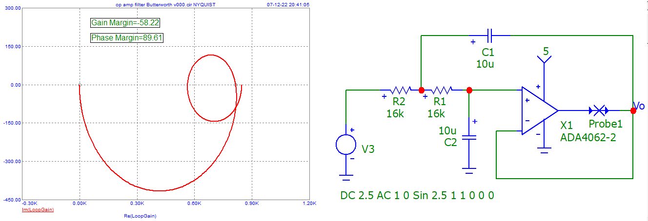
For reference, here is a simulation showing the currents through the capacitors.
You should note that they are very "low" ...
And ... quasi "every" op-amp should do ...

enter image description here

enter image description here

Note the different "constants" (rising and falling).

TRAN Analysis, sinusoidal, 0.1 Hz and 1 Hz.

enter image description here

enter image description here

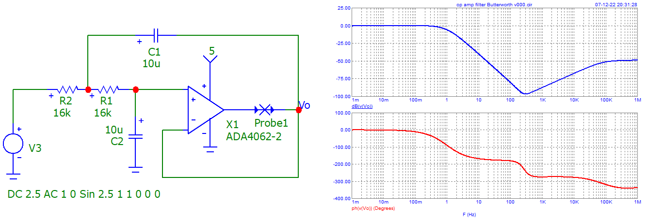
AC Analysis (Closed Loop)

enter image description here

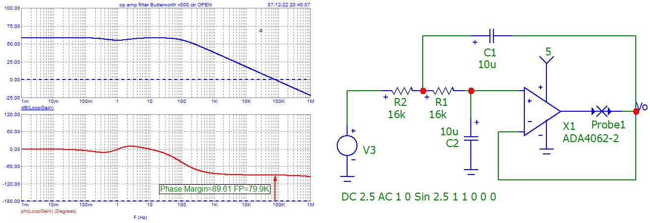
Open Loop, Bode, Nyquist (simulator configuration, not checked)

enter image description here

enter image description here

\$\endgroup\$
2
  • 1
    \$\begingroup\$ Since you have the model up and running in the simulator already, are you able to get phase margins or loop gain plots for these feedback systems? The question ultimately ties back to stability. \$\endgroup\$
    – nanofarad
    Commented Dec 6, 2022 at 20:53
  • \$\begingroup\$ Don't have ADA4523 in the database. Adding only "closed loop" Bode diagrams. Will add later open loop diagrams. \$\endgroup\$
    – Antonio51
    Commented Dec 7, 2022 at 19:15

Your Answer

By clicking “Post Your Answer”, you agree to our terms of service and acknowledge you have read our privacy policy.

Not the answer you're looking for? Browse other questions tagged or ask your own question.