0
\$\begingroup\$

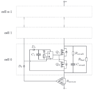
I am interested in designing the autonomous (both turn on and off) high-side high-voltage switch proposed in this paper. The proposed topology of the high-side switch is as follow:

enter image description here

Auto-turning on is quite simple and I have good results in simulation. Now, I want to design the auto-turning off circuit which is a current sensing function, and at predetermined level of current, an hysteresis comparator drive the resets of the RS latches. Main difficulty I am facing to is how to implement the local supply of the current sense (similar to what is done on the gate driver circuit of the MOSFETs). By inspecting how this function is routed on the PCB, I suppose that the local reference (GND) is at the drain of Q2 of the cell 0. enter image description here
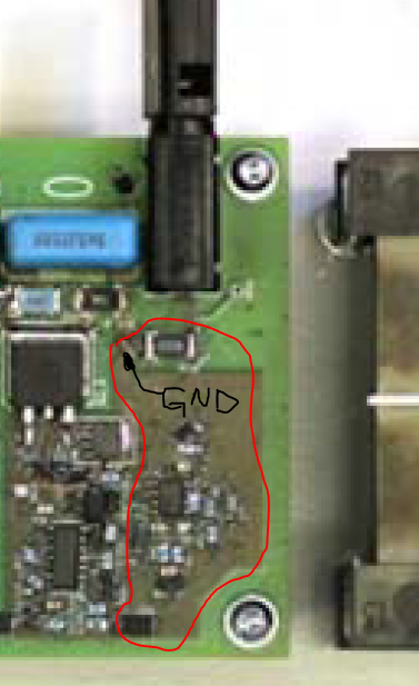
Can you advise me how to implement the local supply for current sensing function?

\$\endgroup\$
4
  • \$\begingroup\$ A current transformer could provide the turn off signal. \$\endgroup\$
    – Jens
    Commented Dec 7, 2022 at 22:07
  • \$\begingroup\$ @jens a non-isolated turn of signal is achievable as you can see on the pcb surrounded with red \$\endgroup\$
    – hiak
    Commented Dec 8, 2022 at 8:18
  • \$\begingroup\$ If you already have a solution - what is your question? \$\endgroup\$
    – Jens
    Commented Dec 8, 2022 at 16:50
  • \$\begingroup\$ I do not have a solution. The picture was taken from a paper which claims it is achievable. I think my question is clear: how to design a self-powered current sense in this topology of buck \$\endgroup\$
    – hiak
    Commented Dec 8, 2022 at 17:42

0

Your Answer

By clicking “Post Your Answer”, you agree to our terms of service and acknowledge you have read our privacy policy.

Browse other questions tagged or ask your own question.