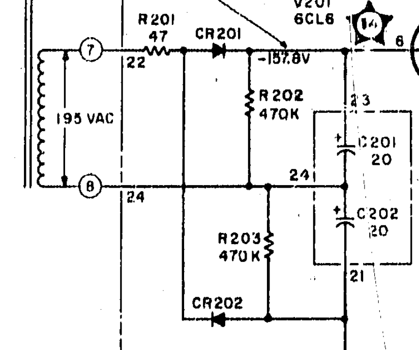
I have a vacuum tube power supply which isn't producing the correct output voltage. I have removed the tube and all that is left is the transformer, inline 22 ohm resistor, CR201/202, R202/203 and C201/202. I simulated it on LTspice and have also included that below. Currently the voltage across C202 is ~90Vdc. I suspect it's due to the capacitors being old and failing - but does anyone have any experience with old caps? Or suggestions? I did increase the voltage from the transformer to 200VAC as that is what the measured value was.

-
1\$\begingroup\$ I can not understand what this question is asking. Add a bit more clarity please. \$\endgroup\$– cats are the bestCommented Dec 7, 2022 at 16:05
-
1\$\begingroup\$ that's an inline 47 ohm resistor ... 22 is associated with the transformer \$\endgroup\$– jsotolaCommented Dec 7, 2022 at 16:08
-
\$\begingroup\$ What is the unit used fro C201 and C202? 20 µF or 20 nF? Are these capacitors wet electrolytic? How old is the supply? \$\endgroup\$– UweCommented Dec 7, 2022 at 16:10
-
\$\begingroup\$ what should the voltage be? \$\endgroup\$– jsotolaCommented Dec 7, 2022 at 16:10
-
1\$\begingroup\$ Have you verified that test points #22 to #24 measure close to 195V AC ? And that AC voltage from #24 to the junction of R201 and CR201 is similar? \$\endgroup\$– glen_geekCommented Dec 7, 2022 at 20:12
1 Answer
If the capacitors are original they are almost certainly bad. If they've dried out you'll get a lot of ripple and low average DC voltage. Old tube equipment that hasn't been used in a long time should be powered up slowly with a variac as old capacitors that have failed shorted can destroy the transformer.
The 47\$\Omega\$ resistor should be checked as it's value may have increased. Carbon composition resistor's values go up as they age, so if it's one of them there's a good chance it's value is off.
This is a voltage doubler circuit, the positive half cycle charges C201, the negative half cycle charges C202, they're in series with balancing resistors across them so the voltages across them add. I can't tell from the part of the schematic shown how it's connected to the rest of the circuit.
