4
\$\begingroup\$

Let's say we set the com-port settings on the PC side with double stop-bit. And then we set the com-port settings on the device side with single stop-bit.

  1. Can we detect stop-bits mismatching with software?
  2. Can we detect stop-bits mismatching with software in Windows?
  3. Can we detect stop-bits mismatching with software in Windows using a standard VCP driver?
\$\endgroup\$
2
  • \$\begingroup\$ Thanks for all answers! Especially from @hobbs. I have find a similar question (electronics.stackexchange.com/questions/454062/…). However, if someone have experienced with double stop-bits checking it will be good to write a comment. \$\endgroup\$
    – Arseniy
    Commented Dec 9, 2022 at 8:21
  • \$\begingroup\$ I'd have put my answer in a comment but the diagrams seemed like they'd be helpful. \$\endgroup\$
    – jonathanjo
    Commented Dec 9, 2022 at 11:13

4 Answers 4

10
\$\begingroup\$

Most PC UARTs under 30 years old only use the "number of stop bits" flag on transmit; on receive they accept any number of stop bits (1 or more). They won't raise a framing error if you are configured for 8N2 and the other end is configured for 8N1 (and the other end won't complain either, since excess stop bits are always acceptable in async serial; they just lower the effective data rate).

I know this for sure for the 16550 (the TI datasheet says "if bit 2 is a logic 1 when either a 6-, 7-, or 8-bit word length is selected, two stop bits are generated. The receiver checks the first stop-bit only, regardless of the number of stop bits selected"), but it's likely also true on common USB-attached UARTs.

If the hardware does detect it, then you'll get a framing error.

\$\endgroup\$
6
\$\begingroup\$

If you specifically want to know what the sender is doing: as opposed to making communications work ...

Background
enter image description here

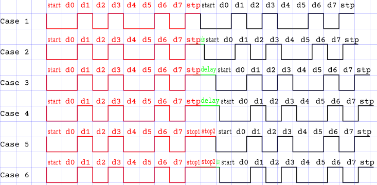
Case 1 is a sender sending back-to-back 8N1 (ASCII 'J' = 0x4a). If the sender is a little slow, we get a short delay (case 2), a whole bit delay (case 3) or more (case 4).

Case 5 is back-to-back 8N2, with a little delay (case 6).

Note that 8N2 is indistinguishable from 8N1 with a 1-bit delay (cases 3 and 5), and so 8N2-with-small-delay is indistinguishable from 8N1-with-longer-delay (cases 4 and 6). Exact 1-bit delay is extremely uncommon.

However, if the baud rate is slow enough or the computer is fast enough, you will have case 1 or 5.

Method 1: Timing

You can tell 8N1 vs 8N2 by timing. If you can get the timing accurate enough, either blocks of data with stopwatch, special program to time incoming bytes (might be tricky in Windows), or oscilloscope.

Method 2: Parity

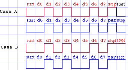
If your sender is sending back-to-back data, you can use the receiver's parity detection to look at the position of the second stop bit. This extends the byte frame by one bit, and now the receiver will check the bit where the second stop bit would be.

Ideally use "Mark" parity (8M1) which sends a 1 for every parity bit, and in fact sends the identical signal to 8N2. But you can do it with even or odd parity (8E1 or 8O1) if you understand that many incoming bytes will have parity errors. (Very briefly: even parity ensures there an even number of 1s in the data+parity bits; odd gives an odd number.)

If you set the receiver to have parity (best is 8M1 where parity is always "Mark", if your receiver will do it, but 8E1 or 8O1 will also work), then you will have either:

  • Case A (red sender sending 8N1 followed by the next byte's start bit, blue what the receiver interprets), which will give a framing error on every byte (and potentially parity errors). Because the receiver will always see the stop bit as a 1, (which might be an error depending on what parity is set), and the new start bit where the stop bit should be, which makes the framing error.
  • Case B (sender sending 8N2), which will not make framing errors. Because the receiver will always see the stop bit as parity=1 (which might be an error), and the second stop bit where a stop bit should be.)
enter image description here

\$\endgroup\$
2
  • 1
    \$\begingroup\$ Even and Odd are not the only options for parity, there's also Mark and Space (which will change decoding of the extra stop bit from 50% error to 100% or 0%) \$\endgroup\$
    – Ben Voigt
    Commented Dec 9, 2022 at 17:31
  • \$\begingroup\$ @BenVoigt Thank you: of course you're right, and in fact 8M1 is simplest. I updated my answer to accomodate. \$\endgroup\$
    – jonathanjo
    Commented Dec 10, 2022 at 5:53
5
\$\begingroup\$

Possible, yes, but it depends on the hardware, and maybe on drivers. It is very unlikely though. Not many hardware chips even verify both stop bits, just one.

The receiver also cannot detect the difference between 1 and 2 stop bits if there is a pause between the frames.

If the hardware checks both stop bits, then only if the other device sends two frames with no gap between them, only then will the receiver see that the second stop bit was violated.

Many UARTs just check if there is a single stop bit and still allows reception of only 1 stop bit even if configured for 2 stop bits, and only the transmit side uses the stop bit setting.

If the hardware detects this error condition in one or both stop bits, the Windows driver will notify user with Framing Error event.

So,

  1. Yes, software gets the information from hardware, if hardware supports checking it, and hardware really checks for both stop bits, and the other device sends two frames back-to-back because a singme frame or two frames sent with a pause in between will not violate the requirement of two stop bits.

  2. Yes, this is exactly same as 1)

  3. Yes if the hardware sends the happened errors to PC, and if the receiver even enforces the requirement for 2 stop bits. Which means there must be a physical UART transmission at some point. Communicating directly to something which looks like COM port but does virtual communication with no UART then there is no physical UART frames so there can be no framing errors as there is no stop bits either.

\$\endgroup\$
1
\$\begingroup\$

The Arduino MCU ATmega328P datasheet says that

The Receiver and Transmitter use the same setting. Note that changing the setting of any of these bits will corrupt all ongoing communication for both the Receiver and Transmitter. An FE (Frame Error) will only be detected in cases where the first stop bit is zero.

The STM32F10x MCU reference manual says that

2 stop bits: Sampling for 2 stop bits is done on the 8th, 9th and 10th samples of the first stop bit. If a framing error is detected during the first stop bit the framing error flag will be set. The second stop bit is not checked for framing error

The NCT6776D Super-I/O IC datasheet says that

NSER (No Stop Bit Error). This bit is set to logical 1 to indicate that the received data have no stop bit. In 16550 mode, it indicates the same condition for the data on the top of the FIFO. When the CPU reads USR, it sets this bit to logical 0.

Thuse it refers to another IC - PC16550D. And the PC16550D datasheet says that

If bit 2 is a logic 0, one Stop bit is generated in the transmitted data. If bit 2 is a logic 1 when a 5-bit word length is selected via bits 0 and 1, one and a half Stop bits are generated. If bit 2 is a logic 1 when either a 6-, 7-, or 8-bit word length is selected, two Stop bits are generated. The Receiver checks the first Stop bit only, regardless of the number of Stop bits selected.

So, in general, it is not customary to control the second stop bit.

\$\endgroup\$
5
  • \$\begingroup\$ Not customary, but with the versatile UARTs of microcontrollers, including the AVR and STM32 you mentioned, it is easily possible to check both stop bits. Even DMX512 standard suggests to check both stop bits if possible, but allows checking only the first. \$\endgroup\$
    – Justme
    Commented Dec 9, 2022 at 17:44
  • \$\begingroup\$ I don't understand a little, how to check both stop bits with the STM32 when its datasheet says the opposite. It says that corresponding frame error flag of the USART register does not rise if second stop-bit corrupted (without any exception). Do you mean an USART emulatuon with the software? \$\endgroup\$
    – Arseniy
    Commented Dec 9, 2022 at 19:40
  • 1
    \$\begingroup\$ No software emulation. Set the MCU UART to 9N1 format and check the 9th data bit yourself, that's the first stop bit, the second stop bit is handled by hardware as the real stop bit. \$\endgroup\$
    – Justme
    Commented Dec 9, 2022 at 22:31
  • \$\begingroup\$ "9N1 format and check the 9th data bit yourself" sounds like semi-software solution. It does't work for 9N2 format and it does't work on MCUs with 8-bit register for received data. But it's a very interesting trick. Thank you. I think we can say that the manufacturers of MCUs and UART bridges commonly do not provide a fully hardware solution for second bit checking. Which means that this check de-facto is considered redundant. \$\endgroup\$
    – Arseniy
    Commented Dec 10, 2022 at 16:58
  • \$\begingroup\$ It works on any MCU that supports 9 bit data setting. AVR is an 8-bit MCU with 8-bit registers, and yet it supports 9 data bits. The register bitness has really nothing to do with that. If an MCU does not support 9 data bits then this check can't be done. And yes, does not work for 9N2 formats, but 9 bit data is not supported by PCs anyway. \$\endgroup\$
    – Justme
    Commented Dec 10, 2022 at 20:23

Not the answer you're looking for? Browse other questions tagged or ask your own question.