5
\$\begingroup\$

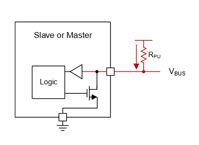
It seems pretty standard to place only 1 pair of pull-up resistors near the master chip, like shown in this diagram from a TI note on I2C.

enter image description here

But I've come across one circuit in my line of work that is incorrectly wired like this:
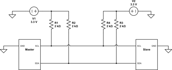
schematic

simulate this circuit – Schematic created using CircuitLab

Both the slave and the master have their own set of pull-ups, with their own voltage sources. This does not work. But if you remove R4 and R3, everything works great... But why would those two extra resistors cause issues? Could it be some timing delay as the bus goes low or high on one end of the communication?

Unfortunately I can't post the entire schematic but the master chip is an MCU and the slave chip is a generic DAC with some registers. Neither chip have internal pull-up resistors.

\$\endgroup\$
4
  • \$\begingroup\$ Isolated 3.3V, gnd can inject DC-DC CM noise. \$\endgroup\$
    – D.A.S.
    Commented Dec 14, 2022 at 21:59
  • \$\begingroup\$ It seems you may have a test failure. Can you describe your results with voltage levels. \$\endgroup\$
    – D.A.S.
    Commented Dec 14, 2022 at 22:04
  • \$\begingroup\$ Is there an expectation that the as-built circuit will have a long line between the Master and Slave, with a relatively high resistance? \$\endgroup\$
    – MikeB
    Commented Dec 15, 2022 at 10:49
  • \$\begingroup\$ @MikeB No it's not a particularly long line. In this case it is not a signal transmission problem. But if it was a long line, i'd be interested to know what kind of signal propagation issues would arise. \$\endgroup\$
    – BobaJFET
    Commented Dec 15, 2022 at 13:46

3 Answers 3

11
\$\begingroup\$

Having two sets of pull-up resistors means the resistances are effectively in parallel. When both have the same value, the equivalent resistance is halved. Correspondingly, the current that each device's output element must sink is doubled.

Most likely, one or more of your devices can't sink enough current to pull the bus down below the logic low threshold. This should be observable on an oscilloscope.

I believe the original I2C specification required output drivers to be able to sink 3 mA of current. In your schematics with 3.3 V and two 2 kΩ resistors in parallel, the sink current is 3.3 mA, above the limit.

\$\endgroup\$
13
  • 4
    \$\begingroup\$ @BobaJFET they're effectively in parallel in the sense that the current flowing into the line is the sum of the current across each resistor. \$\endgroup\$
    – TypeIA
    Commented Dec 14, 2022 at 21:27
  • 1
    \$\begingroup\$ "If the voltage sources had different voltage, would we still consider them to be in parallel?" The resistors would not literally be in parallel but the effect is similar and that's the point TypeIA was correctly making: you've got more current flowing into the driving IC pins and those pins have to be strong enough to sink it. \$\endgroup\$
    – TonyM
    Commented Dec 14, 2022 at 21:53
  • 5
    \$\begingroup\$ @BobaJFET the terminology isn't breaking your circuit. The extra sink current is. Tweaking the scenario to make a term in my explanation not fit won't improve your understanding or fix the circuit. "Effectively in parallel" is a good fit because the effect on the bus is the same. \$\endgroup\$
    – TypeIA
    Commented Dec 14, 2022 at 21:58
  • 2
    \$\begingroup\$ @TonyM - Hi, Re: "actually 2K is correct when referring to the part and what it's labelled, at which point it's a proper noun (a '2K' resistor)" FYI using capital K is not a universal convention (I hadn't heard of it before) and Horowitz & Hill disagree with you in "The Art of Electronics" (this clip from 3rd Edition, page 5 on resistors) where they say: "Thus, a 4.7 kΩ resistor is often referred to as a 4.7k resistor". Note the small "k" in "4.7k resistor". \$\endgroup\$
    – SamGibson
    Commented Dec 14, 2022 at 22:09
  • 1
    \$\begingroup\$ Another sim to further confirm the answer. I think better terminology could be used to describe what's happening aside from the resistors being "effectively in parallel" but I do totally see what TypeIA is saying now. tinyurl.com/2k7xh6me \$\endgroup\$
    – BobaJFET
    Commented Dec 14, 2022 at 22:31
2
\$\begingroup\$

I2C is a slow transmission line. Terminating at both ends when rise time is far greater than the propagation ime delay [ns]. i.e. poor SNR results in poor communication error rates.

enter image description here ...

\$R_{OL}=V_{OL}/I_{OL}= 0.4~ V_{max}/ 3~ mA = 133 ~\Omega \$ -40 to 125 'C
\$ V_{IL}= 0.3 ~V_{DD} = 1 ~V\$

For two 1k pull-ups, using KVL in theory, \$V_{IL}=\dfrac{133 }{133+500}= 0.21 V_{DD}\$ which is less than \$0.3 V_{DD}\$ but supply DC-DC common mode (CM) noise degrades signal quality and performance, resulting in logic errors.

Reducing pullup by two shunts twice the stray noise but not if it is common mode.

Try STP or UTP cable and compare signal quality or remove 1k. Whichever looks better and meets spec will work.

\$\endgroup\$
1
\$\begingroup\$

The only downside is that the total resistance in parallel might be too low and too much current flows.

Depending on the MCU and the sensor, one or both of them may have outputs that are too weak to drive the total resistance. At least in the sense that the chip pulling the voltage down cannot pull the voltage low enough for the other chip to register that as logic low.

Better look at chip data sheets how much current they can safely handle. And better check if the voltages on the bus are within the specs of input logic levels of the chips.

Sure, the I2C specs defines these voltages and currents, but a component you can buy may be compatible with it or work in practice under some conditions, so the chips are not necessarily compliant with the specs.

Some chips have strong outputs that can drive the bus at 6mA specs. Some chips may have weaker outputs and can't even drive the required 3mA.

Your resistance values exceed the 3mA. It is also possible your MCU IO pins are incorrectly configured for driving the bus instead of the required open drain mode.

The bus will not generally be long enough to have the need to take time of flight of the signal into account, so two sets of pull-ups should not matter. So technically the schematics with dual pull-ups are not wrong, just the resistor values.

If the resistors are not connected to the same 3.3V supply, but for example two different 3.3V supply where the other supply can be turned off by the MCU, then it will be a completely different, larger problem.

\$\endgroup\$
5
  • \$\begingroup\$ The resistors are not in parallel. But they're "effectively in parallel" as the other answer stated. I would fix that because it's misleading. Parallel is a very specific term. \$\endgroup\$
    – BobaJFET
    Commented Dec 14, 2022 at 22:35
  • 3
    \$\begingroup\$ They are, effectively, and actually, in parallel, because they simply are just directly in parallel. There is nothing misleading about the schematic. Two resistors from same node pulling to same 3.3V voltage. Parallel. What it would even mean if they are only effectively in parallel but not actually? Current would still be twice the current of single 2k pull-up, being "effectively", or "having the same effect as" a 1k ohm pull-up. \$\endgroup\$
    – Justme
    Commented Dec 14, 2022 at 23:28
  • \$\begingroup\$ The sources are separate which is why i would not consider them “actually” in parallel. But I agree that you can “effectively” treat them as parallel and even combine them as equivalent to get the same effect on the bus. But if they were “actually” in parallel then they would have the same voltage regardless of the source. But in this schematic, if you were to change one of the voltages, the resistors will have different voltage. Look at the sim I posted and change the voltages around or hand calculate it yourself to see. \$\endgroup\$
    – BobaJFET
    Commented Dec 15, 2022 at 12:13
  • \$\begingroup\$ @BobaJFET But in your ideal case, both supplies have identical 3.3V voltage. So the difference is 0V, and voltage sources have zero impedance. So in a simulation, the 3.3V nodes have a virtual short circuit between them. In real life one regulator might be 3.25 and the other 3.35 V and a small current would always flow through the resistors, and would be a problem if the regulators start at different rate or at different time. Nevertheless the semantics or wording, the combined pull-ups are too strong. Just don't back-feed an unpowered chips via pull-ups unless data sheet says it is OK. \$\endgroup\$
    – Justme
    Commented Dec 15, 2022 at 16:10
  • \$\begingroup\$ Agreed. Too much current is absolutely the problem nailed right on the head. What I am trying to say is that for two resistors to be in parallel, they must share the same nodes on both ends, which they don't here, hence they are not truly in parallel. But in this particular setup, they should behave very much like they're in parallel. \$\endgroup\$
    – BobaJFET
    Commented Dec 15, 2022 at 16:33

Your Answer

By clicking “Post Your Answer”, you agree to our terms of service and acknowledge you have read our privacy policy.

Not the answer you're looking for? Browse other questions tagged or ask your own question.