I am trying to communicate between two STM32-based devices using infrared light. The first device is the official STM32L0538-DISCO development board, the second is a Chinese mini board based on the STM32F103C8T6; they are also called Blue Pill.
I use transmitters on TFDU6102, according to the schematic that is given in the datasheet as recommended (I made two small printed circuit boards / two modules).
At the moment, I just want to make a loop to send data from one device to another, receive this data, and return it back to the first. I tried different configuration options, different speeds and modes of operation of the IrDA UART, but it never worked.
This is how I send data from one board to Bluepill:
HAL_IRDA_Transmit(&hirda2, (uint8_t *)"Hello, world!\r\n", 15U, 250U);
But there is a problem with getting data, I call it before the main while loop:
HAL_IRDA_Receive_IT(&hirda2, receiveBuffer, 1U);
And I also have a method to handle the interrupt:
/* USER CODE BEGIN 4 */
void HAL_IRDA_RxCpltCallback(IRDA_HandleTypeDef *hirda)
{
    uint8_t recivedByte = receiveBuffer[0];
    receiveBuffer[0] = 0;
    //IrdaNetwork_ReciveByte(recivedByte, 0U);

    HAL_IRDA_Receive_IT(&hirda2, receiveBuffer, 1U);
}
/* USER CODE END 4 */
I post a bare CubeIDE project, where I just try to read byte by byte IrDA - BluePill_2.
- The modules on the TFDU6102 are working, if you connect each one to the STM32L0538-DISCO, then they work correctly, both for reading and for writing.
- Reading bytes, not through interrupts, on the Blue Pill also does not give results.
- The interrupt for reading on the Blue Pill itself seems to work, if you shine with the remote control (I have it from a floor fan), then sometimes it happens that it reads something, some random byte. I understand that the remote is not IrDA, but just as a clue.
- The transfer from Bluepill to another board via IrDA is correct and without errors. The problem is in reading.
- Exchange just via UART works correctly.
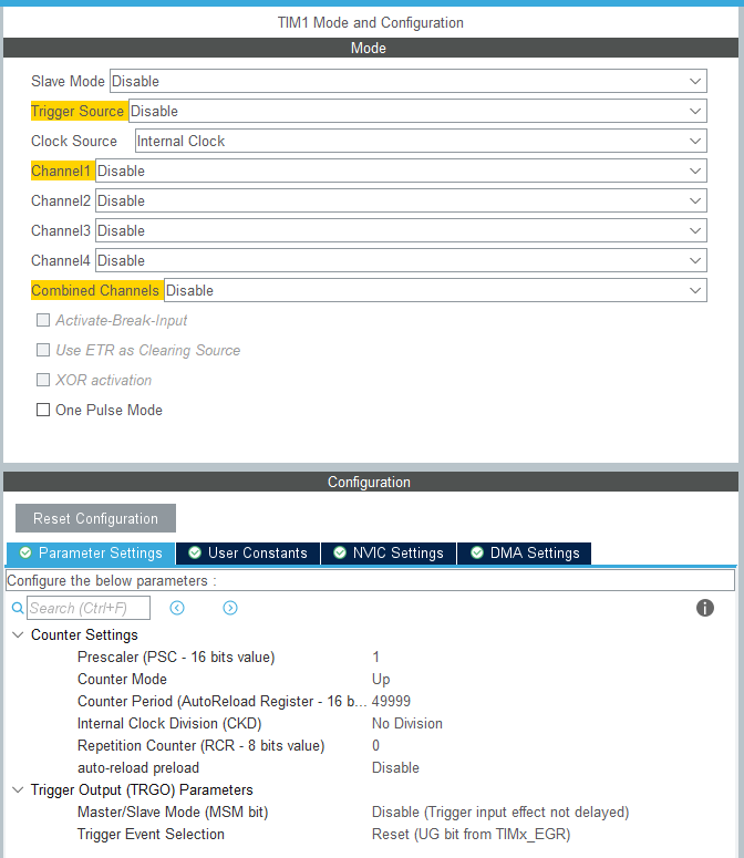
In an attempt to find the problem, I decided that I needed to record the signal that comes from the RX leg - TFDU6102. I set up the TIM1 timer as in the screenshot: 
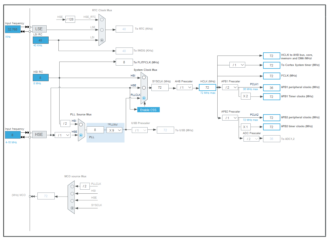
 This should enable me to record the entire transmission signal of my message. I have 15 characters, that's 120 bits + 30 bits for stop/start bits. At a speed of 115200, this is approximately 1.30208 ms. The timer counts down the period in 1.39 ms. I write a signal through interrupts with the following code:
void HAL_GPIO_EXTI_Callback(uint16_t GPIO_Pin)
{
    uint16_t currentCounter = __HAL_TIM_GetCounter(&htim1);
    pinTimeArray[pinArrayIndex] = currentCounter;
    pinArrayIndex++;
}
I get the following spacing values:
32816, 32876, 33128, 33188, 33441, 33501, 33752, 33812, 34377, 34437, 34688, 34748, 35312, 35372, 35937, 35997, 36560, 36620, 37184, 37244, 37496, 37556, 38432, 38492, 39057, 39117, 39368, 39428, 39680, 39740, 40616, 40676, 41552, 41612, 42176, 42236, 42488, 42548, 42800, 42860, 43736, 43796, 44672, 44732, 45298, 45358, 46856, 46916, 47792, 47852, 48417, 48477, 48728, 48788, 49040, 49100, 49976
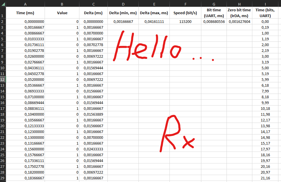
I assume that the first element is a reference point and by calculations I get the following table with times (where the last column is the time of the bits if they were transmitted simply by uart): 
This is what the graph looks like, according to the last column. It seems to me that it fully complies with the IrDA protocol:  We get the bits - 00010010, which corresponds to the letter H (although the order of the bits is inverted). After goes - 10100110, this is the letter e. The minimum pulse of a zero bit is 0.00166667. For a speed of 115200, where the time per bit would be 1/115200 * 1000 - 0.008680556 ms for a standard UART, and multiplied by 3/16 (for IrDA), we get 0.001627604 ms. So the timing is right too.
Please let me know what what am I doing wrong, or what feature am I not aware of? Thanks!

And another question, ....... what is your first question? \$\endgroup\$