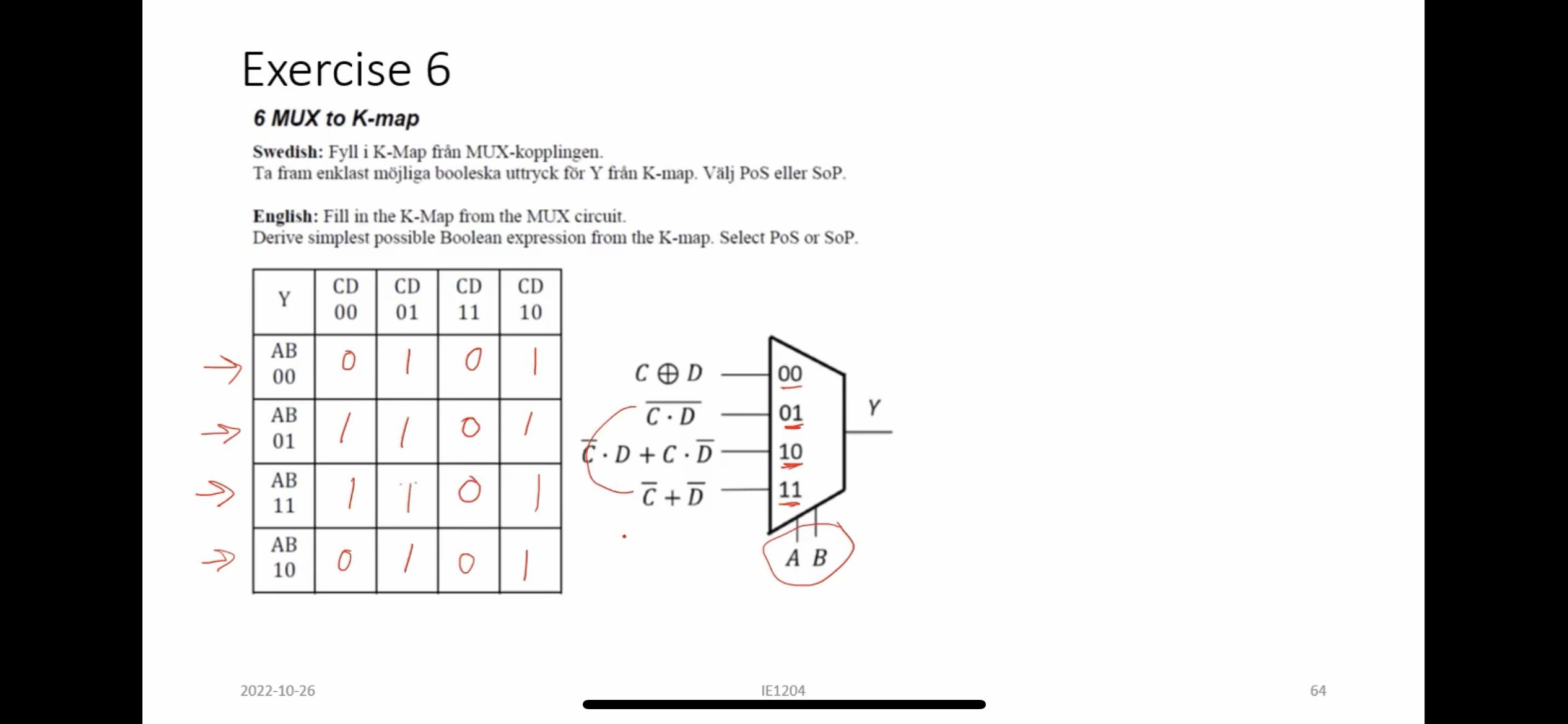
The multiplexer is just a logic circuit, and like any logic circuit, it can be decomposed into a Karnaugh map (K-map). In this case, your circuit has four inputs: \$A\$, \$B\$, \$C\$, and \$D\$, and one output, \$Y\$. Ultimately, by using a K-map, you're hoping to find a simpler, more-efficient way of implementing this same circuit.
Remember that a multiplexer is just a way to select which input to pass through to the output. Internally, they are just a set of logic gates, but that's not important here; all you need to worry about is its function. In this case, you have:
- When \$A = 0\$ and \$B = 0\$, the output is \$Y = C \oplus D\$.
- When \$A = 0\$ and \$B = 1\$, the output is \$Y = \overline{C \cdot D}\$.
- When \$A = 1\$ and \$B = 0\$, the output is \$Y = D \cdot \overline{C} + C \cdot \overline{D})\$.
- When \$A = 1\$ and \$B = 1\$, the output is \$Y = \overline{C} + \overline{D}\$.
Note that even though the K-map's far-left column says AB, and beneath it 00, that's not an AND; in this situation it's just shorthand for A = 0 and B = 0. If it helps, you can think of this as a two-bit binary number (which, of course, has four possible values, thus the four rows). Formally, it's telling you the value of a two-bit vector made from concatenating \$A\$ and \$B\$.
Then you just transfer each function into the K-map. When AB = 00, you enter the result of C xor D for each possible value of \$C\$ and \$D\$. And so on for each row.
You've already done this part successfully, in your example.
I was wondering what difference it would make if I had CD as selector signals instead of the usual AB?
This is an insightful question. You can absolutely design a functionally-identical multiplexed circuit such that the input selection signals are \$C\$ and \$D\$, and the functions being selected from are functions of \$A\$ and \$B\$.
To do this, draw a multiplexer with C and D at the input select. Next, look at what happens when you hold \$C\$ and \$D\$ constant. For example, if C = 0 and D = 0, you have the first column on the left of your K-map; can you simplify this column into a function of \$A\$ and \$B\$? (Hint: look at what happens when B = 0, and when B = 1, and then see what effect the value of \$A\$ has on the output.)
You can do the same for the functions in the other three columns. (You should find particularly-simple functions for these columns!)
In general, the next step in a K-map will be to group all the 1's together into contiguous 'rectangular' loops. You then factor out any signals that don't effect the output for that loop, AND that loop's remaining signals together, then OR the loop results together to get the final circuit.
For example, one loop is a square on the middle left, consisting of B = 1 and C = 0. Note how the state of \$A\$ and \$D\$ don't matter here: when \$B\$ is 1 and \$C\$ is 0, \$Y\$ is 1 regardless of what \$A\$ and \$D\$ are doing. Using this loop will result in a \$Y = B \cdot \overline{C}\$ term in your final answer.
I see three loops in this K-map, each with four terms, and at least two ways to draw them. See if you can find both sets!

