1
\$\begingroup\$

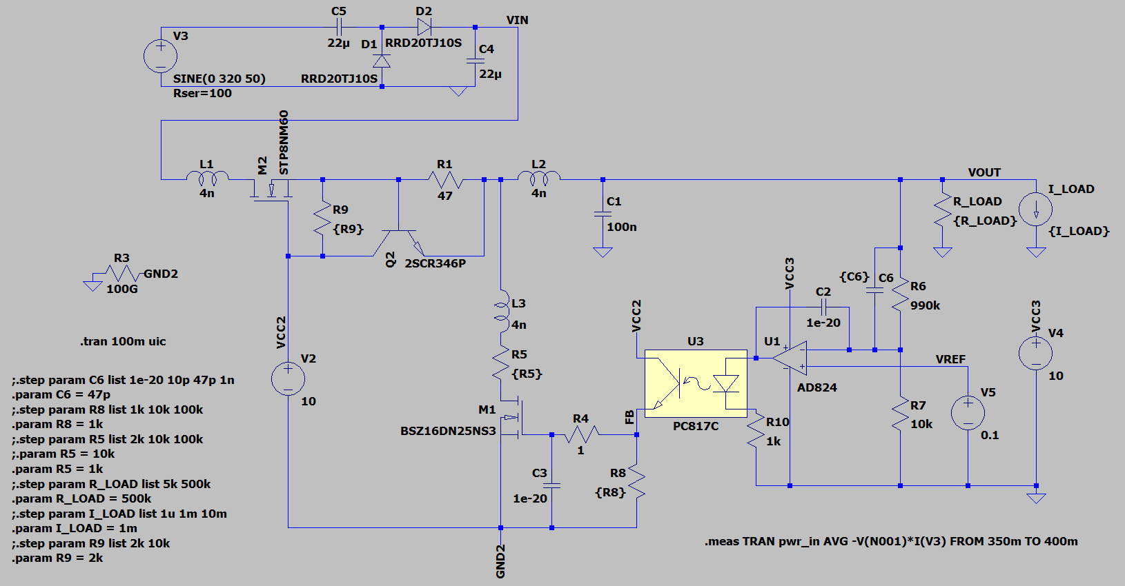
I'm trying to make a capacitor leakage tester and capacitor reformer. I need to create a variable high-voltage power supply for that first. It can provide 0-500 V DC, current limited to 10-15 mA.

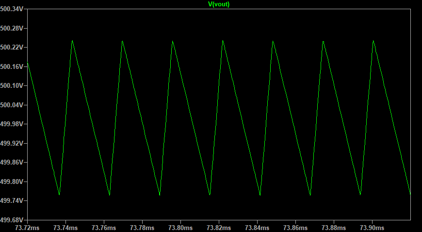
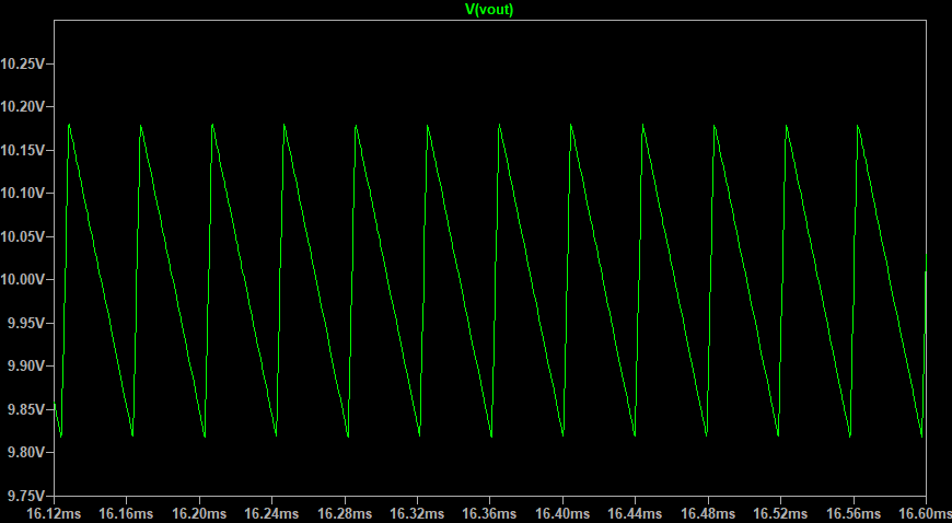
It works fine (in simulation), but there is one problem: the output voltage is oscillating. I tried many changes, but some oscillations remained.
I used components from the LTspice library, it can be changed. I will just use similar transistors or op-amp.

The output voltage is set by "V5", 0.1 V sets 10 V output, 5 V sets 500 V output.

My questions are:

  1. Is it possible to get rid of the oscillations?
  2. In case it is not possible to get rid of them, would it be a problem for measuring capacitor leakage or reforming capacitors?

Schematic:
enter image description here

Oscillations:
enter image description here

enter image description here

SPICE:

Version 4
SHEET 1 2392 1104
WIRE 464 -288 160 -288
WIRE 576 -288 528 -288
WIRE 624 -288 576 -288
WIRE 752 -288 688 -288
WIRE 832 -288 752 -288
WIRE 160 -272 160 -288
WIRE 576 -256 576 -288
WIRE 752 -256 752 -288
WIRE 160 -176 160 -192
WIRE 576 -176 576 -192
WIRE 576 -176 160 -176
WIRE 720 -176 576 -176
WIRE 752 -176 752 -192
WIRE 752 -176 720 -176
WIRE 832 -112 832 -288
WIRE 832 -112 160 -112
WIRE 160 0 160 -112
WIRE 208 0 160 0
WIRE 320 0 288 0
WIRE 464 0 416 0
WIRE 608 0 464 0
WIRE 656 0 608 0
WIRE 768 0 736 0
WIRE 800 0 768 0
WIRE 832 0 800 0
WIRE 992 0 912 0
WIRE 1552 0 992 0
WIRE 1632 0 1552 0
WIRE 1712 0 1632 0
WIRE 1808 0 1712 0
WIRE 1632 16 1632 0
WIRE 1808 16 1808 0
WIRE 464 32 464 0
WIRE 992 32 992 0
WIRE 608 80 608 0
WIRE 992 128 992 96
WIRE 1552 128 1552 0
WIRE 1552 128 1504 128
WIRE 1632 128 1632 96
WIRE 1808 128 1808 96
WIRE 400 144 400 48
WIRE 464 144 464 112
WIRE 464 144 400 144
WIRE 560 144 464 144
WIRE 768 144 768 0
WIRE 768 144 656 144
WIRE 48 176 32 176
WIRE 1504 176 1504 128
WIRE 1552 176 1552 128
WIRE 32 192 32 176
WIRE 800 208 800 0
WIRE 1376 240 1280 240
WIRE 1456 240 1440 240
WIRE 400 288 400 144
WIRE 800 304 800 288
WIRE 1344 304 1344 208
WIRE 1456 320 1456 240
WIRE 1456 320 1376 320
WIRE 1504 320 1504 240
WIRE 1504 320 1456 320
WIRE 1552 320 1552 256
WIRE 1552 320 1504 320
WIRE 400 336 400 288
WIRE 1056 336 1056 288
WIRE 1072 336 1056 336
WIRE 1280 336 1280 240
WIRE 1280 336 1264 336
WIRE 1312 336 1280 336
WIRE 1648 352 1376 352
WIRE 1680 352 1648 352
WIRE 800 400 800 384
WIRE 1552 400 1552 320
WIRE 1680 400 1680 352
WIRE 1072 432 1056 432
WIRE 1280 432 1264 432
WIRE 1056 448 1056 432
WIRE 896 480 848 480
WIRE 912 480 896 480
WIRE 1056 480 1056 448
WIRE 1056 480 992 480
WIRE 1056 528 1056 480
WIRE 896 544 896 480
WIRE 1280 576 1280 512
WIRE 1344 576 1344 368
WIRE 1344 576 1280 576
WIRE 1552 576 1552 480
WIRE 1552 576 1344 576
WIRE 1680 576 1680 480
WIRE 1680 576 1552 576
WIRE 1808 576 1808 368
WIRE 1808 576 1680 576
WIRE 1808 592 1808 576
WIRE 400 656 400 416
WIRE 800 656 800 496
WIRE 800 656 400 656
WIRE 896 656 896 608
WIRE 896 656 800 656
WIRE 1056 656 1056 608
WIRE 1056 656 896 656
WIRE 800 688 800 656
FLAG 992 128 0
FLAG 1632 128 0
FLAG 800 688 GND2
FLAG 32 192 0
FLAG 128 176 GND2
FLAG 1712 0 VOUT
FLAG 1808 592 0
FLAG 400 288 VCC2
FLAG 1056 448 FB
FLAG 1056 288 VCC2
FLAG 1648 352 VREF
FLAG 720 -176 0
FLAG 832 -288 VIN
FLAG 1808 288 VCC3
FLAG 1344 208 VCC3
FLAG 1808 128 0
SYMBOL npn 560 80 M90
WINDOW 3 77 59 VRight 2
SYMATTR Value 2SCR346P
SYMATTR InstName Q2
SYMBOL res 640 16 R270
WINDOW 0 32 56 VTop 2
WINDOW 3 0 56 VBottom 2
SYMATTR InstName R1
SYMATTR Value 47
SYMBOL cap 976 32 R0
SYMATTR InstName C1
SYMATTR Value 100n
SYMATTR SpiceLine V=1000
SYMBOL res 1616 0 R0
SYMATTR InstName R_LOAD
SYMATTR Value {R_LOAD}
SYMBOL res 144 160 R90
WINDOW 0 0 56 VBottom 2
WINDOW 3 32 56 VTop 2
SYMATTR InstName R3
SYMATTR Value 100G
SYMBOL res 1008 496 M270
WINDOW 0 32 56 VTop 2
WINDOW 3 0 56 VBottom 2
SYMATTR InstName R4
SYMATTR Value 1
SYMBOL res 784 288 R0
SYMATTR InstName R5
SYMATTR Value {R5}
SYMBOL voltage 400 320 R0
WINDOW 123 0 0 Left 0
WINDOW 39 24 124 Left 2
SYMATTR InstName V2
SYMATTR Value 10
SYMBOL voltage 1808 272 R0
WINDOW 123 0 0 Left 0
WINDOW 39 24 124 Left 2
SYMATTR InstName V4
SYMATTR Value 10
SYMBOL res 1536 160 R0
SYMATTR InstName R6
SYMATTR Value 990k
SYMBOL res 1536 384 R0
SYMATTR InstName R7
SYMATTR Value 10k
SYMBOL res 1264 416 R0
SYMATTR InstName R10
SYMATTR Value 1k
SYMBOL Optos\\PC817C 1168 384 M0
SYMATTR InstName U3
SYMBOL cap 1440 224 R90
WINDOW 0 0 32 VBottom 2
WINDOW 3 32 32 VTop 2
SYMATTR InstName C2
SYMATTR Value 1e-20
SYMBOL cap 912 544 M0
SYMATTR InstName C3
SYMATTR Value 1e-20
SYMBOL voltage 1680 384 R0
WINDOW 123 0 0 Left 0
WINDOW 39 0 0 Left 0
SYMATTR InstName V5
SYMATTR Value 0.1
SYMBOL nmos 848 400 M0
SYMATTR InstName M1
SYMATTR Value BSZ16DN25NS3
SYMBOL res 1072 512 M0
SYMATTR InstName R8
SYMATTR Value {R8}
SYMBOL res 448 16 R0
SYMATTR InstName R9
SYMATTR Value {R9}
SYMBOL OpAmps\\AD824 1344 272 M0
WINDOW 3 -90 118 Left 2
SYMATTR InstName U1
SYMBOL ind 192 16 R270
WINDOW 0 32 56 VTop 2
WINDOW 3 5 56 VBottom 2
SYMATTR InstName L1
SYMATTR Value 4n
SYMBOL ind 816 16 R270
WINDOW 0 32 56 VTop 2
WINDOW 3 5 56 VBottom 2
SYMATTR InstName L2
SYMATTR Value 4n
SYMBOL ind 784 192 R0
SYMATTR InstName L3
SYMATTR Value 4n
SYMBOL voltage 160 -288 R0
WINDOW 123 0 0 Left 0
WINDOW 39 24 124 Left 2
SYMATTR SpiceLine Rser=100
SYMATTR InstName V3
SYMATTR Value SINE(0 320 50)
SYMBOL cap 736 -256 R0
SYMATTR InstName C4
SYMATTR Value 22µ
SYMBOL cap 528 -304 R90
WINDOW 0 0 32 VBottom 2
WINDOW 3 32 32 VTop 2
SYMATTR InstName C5
SYMATTR Value 22µ
SYMBOL diode 592 -192 R180
WINDOW 0 24 64 Left 2
WINDOW 3 24 0 Left 2
SYMATTR InstName D1
SYMATTR Value RRD20TJ10S
SYMBOL diode 624 -272 R270
WINDOW 0 32 32 VTop 2
WINDOW 3 0 32 VBottom 2
SYMATTR InstName D2
SYMATTR Value RRD20TJ10S
SYMBOL cap 1488 176 R0
WINDOW 3 -50 5 Left 2
SYMATTR InstName C6
SYMATTR Value {C6}
SYMBOL current 1808 16 R0
WINDOW 123 0 0 Left 0
WINDOW 39 0 0 Left 0
SYMATTR InstName I_LOAD
SYMATTR Value {I_LOAD}
SYMBOL nmos 320 48 R270
SYMATTR InstName M2
SYMATTR Value STP8NM60
TEXT 8 304 Left 2 !.tran 100m uic
TEXT -120 376 Left 2 !;.step param C6 list 1e-20 10p 47p 1n\n.param C6 = 47p\n;.step param R8 list 1k 10k 100k\n.param R8 = 1k\n;.step param R5 list 2k 10k 100k\n;.param R5 = 10k\n.param R5 = 1k\n;.step param R_LOAD list 5k 500k\n.param R_LOAD = 500k\n;.step param I_LOAD list 1u 1m 10m\n.param I_LOAD = 1m\n;.step param R9 list 2k 10k\n.param R9 = 2k
TEXT 1184 680 Left 2 !.meas TRAN pwr_in AVG -V(N001)*I(V3) FROM 350m TO 400m
\$\endgroup\$
25
  • 1
    \$\begingroup\$ Where's the time axis in the oscillations? \$\endgroup\$ Commented Jan 12, 2023 at 11:19
  • 2
    \$\begingroup\$ I'm not very keen on test equipment that has a galvanic connection to the live side of AC mains. Wouldn't a more conventional flyback circuit be safer and dissipate less power in the shunt regulator? I suspect that your regulation circuit has hysteresis and will naturally oscillate. \$\endgroup\$
    – Andy aka
    Commented Jan 12, 2023 at 11:30
  • 3
    \$\begingroup\$ At ~1 mA, I see .35 V PP, at 2.5 mA (.5 in voltage divider, ? R_LOAD list 5k…), there's .5 V. I take it to be ripple rather than oscillation. \$\endgroup\$
    – greybeard
    Commented Jan 12, 2023 at 11:36
  • 1
    \$\begingroup\$ @TimWilliams I have updated those charts. \$\endgroup\$ Commented Jan 12, 2023 at 11:37
  • 1
    \$\begingroup\$ You should be aware that your "attenuator" (measuring high voltage) ... is not "frequency compensated", so oscillations on high voltage ... pass quasi-integrally on your AD824 negative input ... \$\endgroup\$
    – Antonio51
    Commented Jan 12, 2023 at 12:03

2 Answers 2

3
\$\begingroup\$

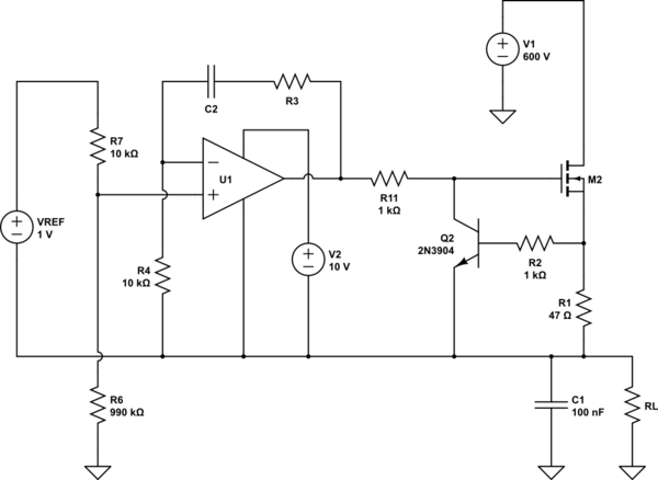
As hinted by my comments, this seems drawn in a confusing way, at the very least; and there seem to be other problems. But that's okay, we're learning here. So let's explore what's going on (or not), what I think you meant, and what the usual ways to go about this are.

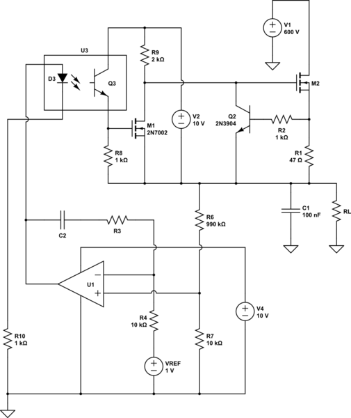
First, this is somewhere between what I thought I read of the schematic, and what I thought you meant:

schematic

simulate this circuit – Schematic created using CircuitLab

Note that the high-side stuff is all drawn isolated from main GND, with what would be GND2 tied with the output, that is, common with the output stage (that is to say, common to M2 source, or something near there; R1 manifests as both current limiting and source degeneration when we view M2 as a common-source amplifier). This would explain why you chose to assign a separate ground. But as it happens, your GND2 varies with respect to the output, making it disingenuous to call "ground"—hence my confusion.

Also just now realizing I missed your R5 (1kΩ), which addresses the current limit concerns I had in comments.

Anyway, following the assumption that GND2 was actually to be a ground with respect to some high-side drive circuitry, and using an opto and another transistor, that might end up looking something like this. Since U3 and M1 end up inverting, U1's inputs are swapped, but that's fine.

And, maybe this misinterpretation is making its own straw men, but the dynamics I think still aren't too far off. So, let's dig into that.

Let's consider what happens when U1 makes a step change in its output.

Now, is this even a reasonable assumption? Op-amps don't make step changes, they are slew-rate limited. So perhaps not. But it's a useful way to think about elements of a loop.

A step increase in U1 output means step current in U3 (it's drawn with "D3" and "Q3" since an opto component isn't in the library), and in turn a change at M1 gate. The current is limited (CTR is in the ballpark of 100%) so the capacitance of M1 will play a role. Namely, we have a pole of M1-Ciss with R8. Note the gate voltage can span the full 0-10V supply range, even though only a tiny range is needed to get M1 between threshold (min Vgs(th)) and saturation (at ID = 5mA, barely above max Vgs(th)), so if this node saturates, it'll take a long time to go up or down into the linear range (M1 between cutoff and saturation).

(Note: I'm using "saturation" exclusively to refer to voltage saturation here. I, for one, would like to disavow the confusing historical terminology of FET [current] saturation. But since that's been the case, it would be remiss of me to not add this note.)

M1 drain, likewise, takes some time to respond. It can drop fairly quickly (limited by Miller effect, anyways), but rise limited by R9 with M2 Ciss (and some Miller effect, depending on output voltage swing).

Both gate voltages being cascaded, introduces two large poles in the control loop, guaranteeing either instability, or such excessive compensation required on the op-amp (certainly more than 10-20 F worth!) that the system will be ponderously slow. And the wide voltage ranges, compared to what actual gate voltage ranges are needed to control it, make startup or saturation recovery especially slow.

And meanwhile, not only are the voltage ranges excessive, but M1 and M2's transconductances vary considerably over that range as well. So even if you get it operating stable at one load (voltage or current), it's probably super slow at low currents, or unstable at high currents.

So, one simple answer would be to increase C2 enough to stabilize things. But this doesn't solve any of the latent problems, or teach very much.


So what do we usually do for something like this?

Two common ways, I would say.

One, we can extend the high-side circuitry to include the error amp itself, and then the voltage sense divider will be "below" the local reference. Roughly speaking, this is how three-terminal regulators like LM317 work.

schematic

simulate this circuit

Note that U1-M2 acts as a boosted voltage follower, i.e. +IN = VOUT. R11 does incur a pole with M2 Ciss, and maybe its value could be smaller (or absent entirely, if we can rely on the op-amp's output current limiting to let Q2 do its job when needed), but that's mostly what the compensation (C2 + R3) will be handling.

And, as mentioned in other comments, some capacitance on R6 and R7 may be desirable to increase phase margin. And maybe some protection like clamp diodes from +IN to VOUT.


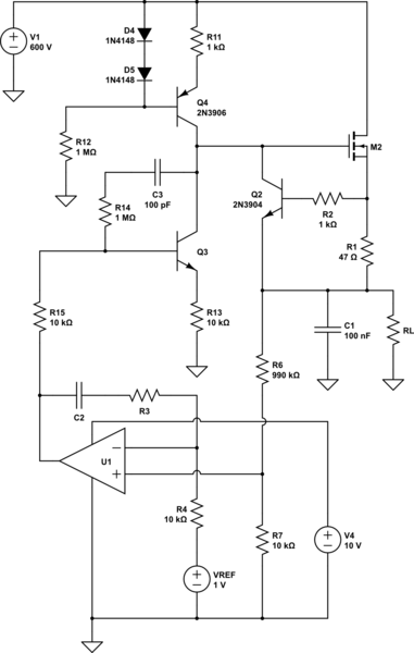
Or, we can keep the low-side error amp, and use a level shifting circuit, designed for stable gain, and matching up the voltage and current ranges at its inputs and outputs so we aren't wasting range.

schematic

simulate this circuit

The simplest level shift will be a common-emitter amplifier, with considerable emitter degeneration, Q3. This gives a constant current, proportional to the base voltage: nearly the full output range of U1 is honored, and a current is pulled down (from the gain node, Q3-C) proportional to that voltage.

Shown here, I've opted to put in a current source pull-up, Q4. This avoids the high-side floating supply, greatly simplifying design. The downside is a higher dropout voltage (a bit over M2 Vgs(th)), but out of 600V, that's a teensy price to pay.

The current source also vastly increases the voltage gain on the gain node (hence... the node with gain, the gain node). This would be a problem for increasing loop gain, so we need to control that. R14+C3 serves as a modified Miller compensation: at high frequencies, C3 looks like a short, and the voltage gain levels off at R14/R15. Which balances with R7/(R6+R7) so the op-amp thinks it's in a unity-gain feedback loop -- it will need little compensation. (Still, adjust C2 and R3, as well as R14 and C3, to see what's needed. C1 as well, and try some ESR on C1 too.)

\$\endgroup\$
6
  • \$\begingroup\$ Thank you for you analysis and suggested solutions. Very good food for thought for me. In the first solution, VOUT is meant as output of opamp or "regulated output" (aka. virtual ground for high-side part)? I assume you meant this virtual ground when talking about clapming diodes. \$\endgroup\$ Commented Jan 24, 2023 at 15:23
  • \$\begingroup\$ In the second solution, gate of M2 is basically like 5-10V above VOUT. VOUT can be between 5-500V, so the gate can be from 10V to 510V, thus both Q3 and Q4 should be high voltage ones. 2N3906 could not be used. Am I right? \$\endgroup\$ Commented Jan 24, 2023 at 15:24
  • \$\begingroup\$ Oh yeah, forgot to delete the type on Q4, '3906 wouldn't go very far indeed. You can also use a pull-up resistor instead of the current source (Q4) if you don't need as much output voltage range. HV PNPs are uncommon so a cascode may be desirable if you need the CCS at high voltages. \$\endgroup\$ Commented Jan 24, 2023 at 18:28
  • \$\begingroup\$ I simulated both suggested schematics. They both work very well. I extremely like the first one. Especially that part around IN+. I really like that idea. btw. it has to be 1meg instead on 990k there to get 1:100 attenuation of VOUT there. Thank you once again. \$\endgroup\$ Commented Jan 26, 2023 at 13:35
  • \$\begingroup\$ Whoops, right you are! \$\endgroup\$ Commented Jan 26, 2023 at 22:20
1
\$\begingroup\$

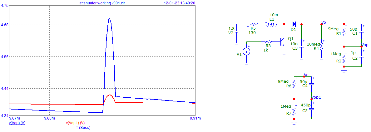
Take into account that your attenuator is not compensated.
So regulation reacts on "fast" transient in the output voltage.
See this, for example, this measuring "error" ...

enter image description here

Here is a simplified circuit simulated ...

Seems that "sign loop" was not ok.

enter image description here

\$\endgroup\$
7
  • \$\begingroup\$ L1, L2, L3 are just parasitic inductances. \$\endgroup\$ Commented Jan 12, 2023 at 13:00
  • \$\begingroup\$ I put C7 parallel to R7. Any value higher than 0p makes ripple higher. \$\endgroup\$ Commented Jan 12, 2023 at 13:13
  • \$\begingroup\$ I'm not sure what to take from your simplified circuit. It seems you used completely different opto, and no "main" transistor (M2). I understand you see problem in compensation, but I do not know how to compensate it. \$\endgroup\$ Commented Jan 14, 2023 at 21:36
  • \$\begingroup\$ M2 and Q2 is a "current" limiting circuit. I replaced it by my 10k resistor. Ok, it is or the "same" circuit but I used it for testing the regulator circuitry (right part of the design). As PC817 is not in my "library", I used "equivalent" 4N33 (?) which does not change really the behavior. Compensation is done simply: your R6 x C6 = R7 x C7. C6= ~ 5 pF. As R6= ~100 x R7 then C7 = ~ 100 x C6 = 500 pF. \$\endgroup\$
    – Antonio51
    Commented Jan 14, 2023 at 21:54
  • \$\begingroup\$ I noted that your circuit was not "stable" with Opto wired as you did ("follower"). I change it to "inverter" and then it was "stable". So, I could add an effective and useful capacitor (my C1) wired with op-amp as an integrator and C7. Note that "rise on" time is not the same as "rise down" timing at output Vo. \$\endgroup\$
    – Antonio51
    Commented Jan 14, 2023 at 22:00

Your Answer

By clicking “Post Your Answer”, you agree to our terms of service and acknowledge you have read our privacy policy.

Not the answer you're looking for? Browse other questions tagged or ask your own question.