0
\$\begingroup\$

I purchased the MP3 Jukebox module (manual) from Velleman (ref. VM202N).

I have some trouble making the connections on my breadboard.

Here is what I think is the best I can do:

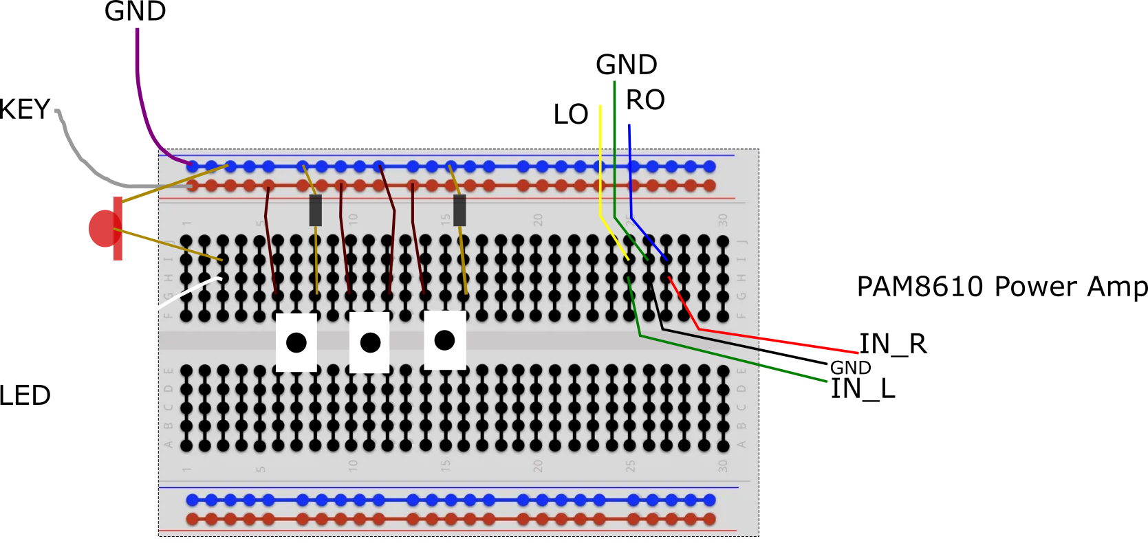
enter image description here

The result is that the music plays correctly (it is amplified too much by the power amp though, given my 8 Ω, 0.5 W speakers), the LED is blinking together with the input level, but the push buttons don't do what they should do:

  1. None of the buttons connected to a resistance really works
  2. The only push button connected without a resistance doesn't do the "previous song" action. Instead, it lowers the volume if I keep it pushed, and, when released, the volume goes back to max.

My only guess so far would be that I should use reversed buttons, but it doesn't work either when I try to fake reverse behavior (using my finger to hold the buttons down, and removing one of them to trigger a "click").

I don't want to rush into buying new buttons if the error is elsewhere.

PS: The values of the resistors are correct. I double-checked multiple times.

  • The purple wire connected to the "-" (blue lane) on the schematic is the GND corresponding to wire 3 in the manual.

  • The grey wire connected to the "+" (red lane) on the schematic is the KEY corresponding to wire 2 in the manual

  • The white wire connected to the led (3rd column from left) on the schematic is the LED corresponding to wire 1 in the manual.

  • All the push buttons on the schematic have their left pin connected to the red lane (KEY) and the right pin connected either directly (center button) to the blue lane (GND), or with an intermediate resistor (left button and right button).

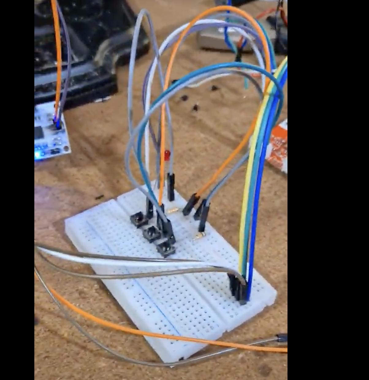
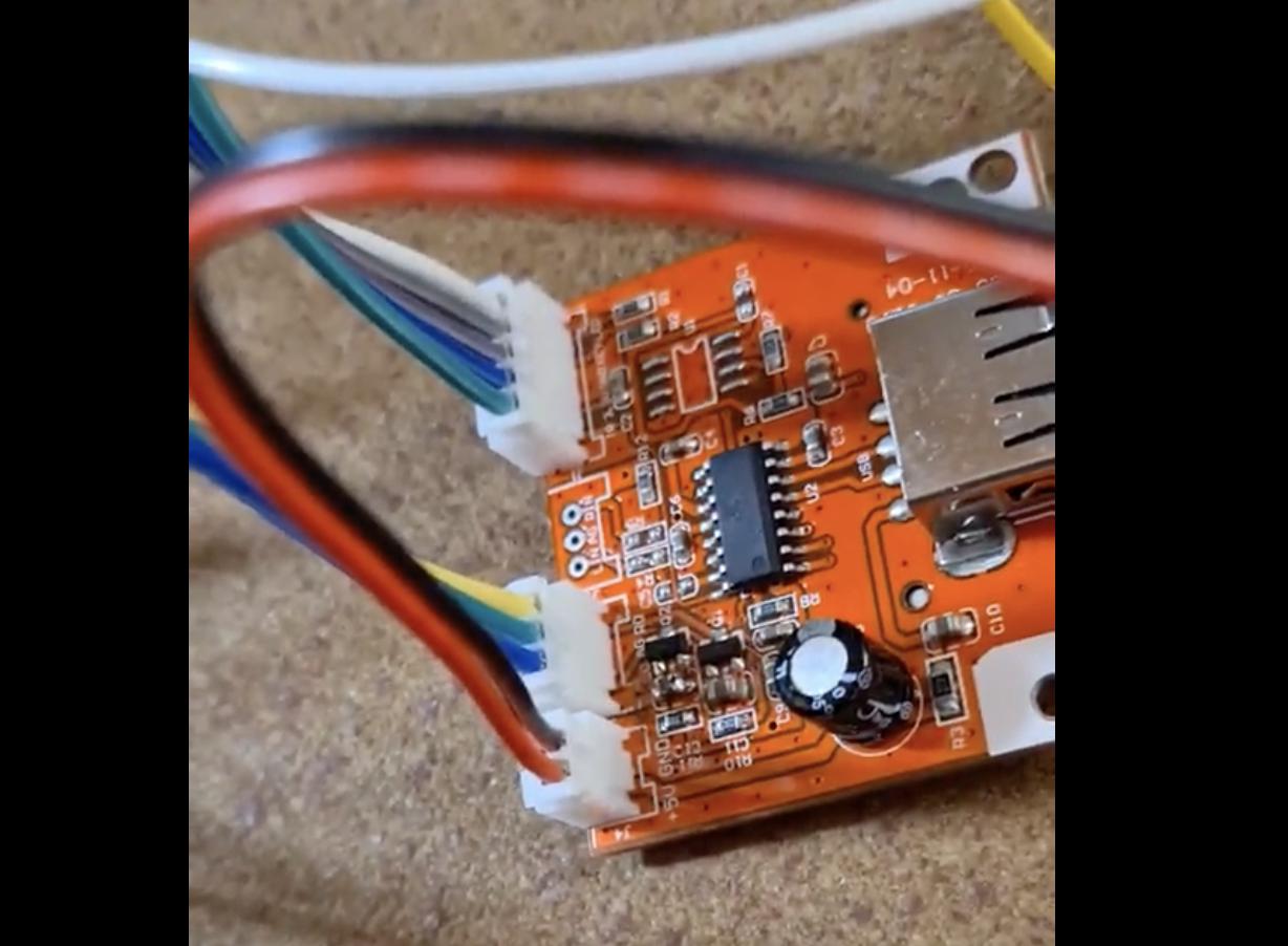
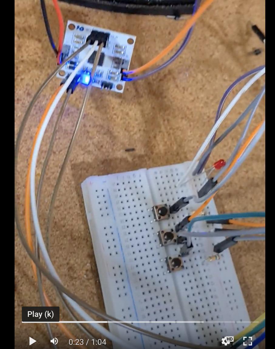
The purple, grey, and white color coding is visible on the pics below, specially on the second one.

Here are some more pics:

enter image description here

enter image description here

enter image description here

\$\endgroup\$
15
  • 1
    \$\begingroup\$ Please show a schematic of how your buttons and resistors connect to the module. Please also provide a link to the document that explains how the "key" input works on the module. Pictures show nothing really. So much more is shown in a schematic. \$\endgroup\$
    – Andy aka
    Commented Jan 12, 2023 at 16:05
  • \$\begingroup\$ basic datasheet/brochure: quasarelectronics.co.uk/manuals/velleman/… - the "key" wiring is shown in the bottom-right. Although I hate these products that don't provide proper datasheets, it does show the needed external wiring. \$\endgroup\$ Commented Jan 12, 2023 at 16:13
  • \$\begingroup\$ There's probably nothing wrong with the buttons themselves. What value resistors did you use? \$\endgroup\$ Commented Jan 12, 2023 at 16:14
  • \$\begingroup\$ I added written explanation of the schematic to help make the parallel with the manual's description, @Andyaka \$\endgroup\$
    – Myoch
    Commented Jan 12, 2023 at 16:20
  • \$\begingroup\$ @user253751, I used the resistors that came with the kit, namely one 15kOhm (was 14.8 on my multimeter) for the "prev" button" and one 33 kOhm for the pause button (was 32.4 on my multimeter). If it's not the resistors nor the push buttons, could it be the power supply? I'm not so sure how much I should put. I tried 9V for the jukebox (with the adapter) and 12V for the amp, but that gives the same results if I only put 6V for the amp, or if I remove the adapter and provide only 5V for the jukebox module... I'm a bit confused. \$\endgroup\$
    – Myoch
    Commented Jan 12, 2023 at 16:25

0

Your Answer

By clicking “Post Your Answer”, you agree to our terms of service and acknowledge you have read our privacy policy.