My question is about wiring a "floating differential input" signal to an instrumentation amplifier.
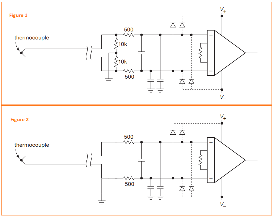
I've read that in the case of a floating signal two high value resistors are used to provide DC bias for the amplifier inputs as shown in Figure 1 below(the 10k resistors in this case):
As you see in Figure 1, the two 10k resistors are used for such purpose and my questions are:
1-) If the 10k resistors in Figure 1 were not equal what would change at the output?
2-) Looking at Figure 2 above: if we don't use such resistor pair but instead if we just ground one end of the input signal, what would be the consequences?

