0
\$\begingroup\$

I have got a few Hall-effect sensors, the VF460S from Honeywell.

Now I try to make a circuit using a microcontroller Raspberry Pi Pico to read the output. I have connected V-supply pin to 3v3 gpio, Ground pin to ground on the microcontroller and the output-pin to a gpio pin that is configured to be a digital-input pin.

I don't get any result from Hall-effect sensor to the digital-input on the microcontroller (it should turn off a LED, in my program), when I put a strong neodymium-magnet nearby the sensor.

I am new to electronics, and perhaps I have misunderstood the datasheet or a wrong type of sensor.

I have also tried with a different Hall-effect sensor from the same bag. From what I understood, this sensor should work with 3v3 V-supply. I also tried to replace the sensor V-supply and Ground pin, with a LED, temporary and it did turn-on.

Is there anything I have misunderstood with the usage of the digital hall-effect latch sensor VF46S? Is there any other way to test it?

\$\endgroup\$
5
  • \$\begingroup\$ Does your microcontroller function correctly when you connect the input pin to VCC or ground with a jumper wire? \$\endgroup\$
    – vir
    Commented Jan 25, 2023 at 22:43
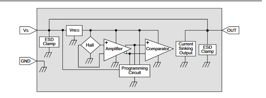
  • \$\begingroup\$ The block diagram indicates "current-sinking output" so maybe try adding a pull-up resistor if you didn't already. Also, it will only activate if the south side of the magnet is closest to the sensor. \$\endgroup\$ Commented Jan 25, 2023 at 22:53
  • \$\begingroup\$ @vir, I connected input-pin to Vcc now, and it works (my coded led does turn off). \$\endgroup\$
    – Jonas
    Commented Jan 25, 2023 at 22:55
  • \$\begingroup\$ @user253751, interesting. I have not added a pull-up. I assume that I should have it from input-pin to vcc. Will test that. \$\endgroup\$
    – Jonas
    Commented Jan 25, 2023 at 22:56
  • \$\begingroup\$ @user253751, thanks. When I added a pull-up resistor from input-pin to Vcc, it works. Now the LED is turning on-off when I turn a magnet. Add it as an answer, and I can accept it. \$\endgroup\$
    – Jonas
    Commented Jan 25, 2023 at 22:59

2 Answers 2

1
\$\begingroup\$

Since the block diagram in the datasheet shows "current sinking output", you might need to use a pull-up resistor to bring the voltage high when the sensor is not sinking any current.

(The block diagram also shows the output being directly connected to Vcc, but then the output would always be high, so I infer that it is probably a mistake in the drawing)

\$\endgroup\$
2
  • \$\begingroup\$ The block diagram shows it being connected to VCC, so this may not be the case. \$\endgroup\$
    – Voltage Spike
    Commented Jan 25, 2023 at 23:12
  • \$\begingroup\$ @VoltageSpike indeed, but if that was the case, the output would always be high, so I infer it is a mistake in the drawing. \$\endgroup\$ Commented Jan 27, 2023 at 16:09
2
\$\begingroup\$

The output is latching, meaning it is either on or off. Use a DMM in continuity mode and see if the block diagram in the datasheet is correct with the output being connected to Vs. If it isn't shorted, then you'll need a resistor from Vs to out, something like 20k would suffice.

Use the DMM again (or oscilloscope) with the resistor attached and you should see the output change when the magnet is moved far away to close.

enter image description here Source: High Sensitivity Latching Digital Hall-effect Sensor ICs: VF360NT, VF360ST, VF460S 32311084 datasheet

\$\endgroup\$
1
  • \$\begingroup\$ I tried to use a multimeter to check the voltage between ground and output-pin of the sensor, it only showed ~0v. I only get a value when I add a resistor between output-pin and Vcc. I only have a basic multimeter to check with. But informative answer, thanks. \$\endgroup\$
    – Jonas
    Commented Jan 25, 2023 at 23:53

Your Answer

By clicking “Post Your Answer”, you agree to our terms of service and acknowledge you have read our privacy policy.

Not the answer you're looking for? Browse other questions tagged or ask your own question.