2
\$\begingroup\$

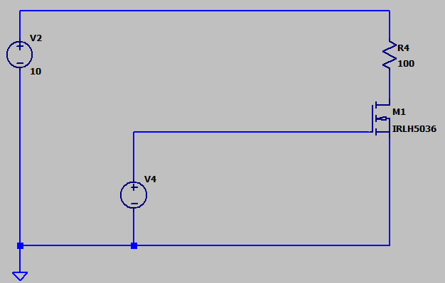
I want to unterstand the process of firing a MOSFET und used an LTspice simulation to see the current flowing into gate capacitance und the resulting drain-source current. For this I used a simplified circuit in LTspice with two voltage sources, one permanent source of 10 V and one single-pulse voltage source for the gate.

I do not understand the simulation result as it shows a negative drain-source current in the first short time interval after pulling the gate to 2.5 V. Notice that I used such a low gate voltage for the MOSFET IRLH5036 to research switching behaviour on low voltage gate inputs e.g. from logic sources.

Here is the waveform. Notice that I multiplied I(R4) with factor 10 to make the effect more visible. The blue waveform drops to -84mA (-8.4 mA without factor mupltiplication) in the beginng. Ig(M1) presents the gate current on triggering at 100ms. I'm well aware that these MOSFETs have an internal reverse diode, but there should be no negative voltage bias over the MOSFET.

enter image description here

Attached here also the used circuit:

Circuit

Any idea why this is occuring? Do you have literature hints?

\$\endgroup\$

2 Answers 2

1
\$\begingroup\$

I do not understand the simulation result as it shows a negative Drain-Source current in the first short time interval after pulling the gate on 2.5 V.

It actually shows a negative drain current (the drain-source current is a meaningless quantity). This drain current will be somewhat mirrored by a positive source current that may be several times bigger (dependent on the MOSFET type).

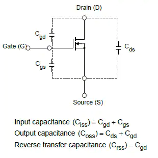
The current you see is the injection of charge, from the gate into both drain and source pins. This will be seen as a short pulse of negative current in the drain. The charge injection is due to inter-electrode capacitances. These are well-known phenomena in MOSFETs.

enter image description here

Image from here.

\$\endgroup\$
0
\$\begingroup\$

I suspect that current flowing into the gate to charge its capacitance, current which has to exit somewhere (by KCL), is leaving via both source (downwards) and drain (upwards), momentarily, as the gate charges.

At some point (probably before the gate has fully charged) the channel becomes conductive enough for current due to V2 to begin to rise, and net drain current crosses zero.

Eventually the gate is charged, all current flowing in the channel is purely due to the EMF of V2 (downwards into the drain), and this "anomaly" is over.

\$\endgroup\$

Your Answer

By clicking “Post Your Answer”, you agree to our terms of service and acknowledge you have read our privacy policy.

Not the answer you're looking for? Browse other questions tagged or ask your own question.